| ||
|---|---|---|
 |
 |
 |
| Click on the above image to go to a page dedicated to the seat shown. | ||
The Mk. 7 family is one of the largest seat families in the world. This Mark designation indicates that the seat is a mechancally timed seat with a combination of catapult (60fps rail separation speed) and a underseat rocket for propulsion. These seats use the same or similar mechanisms as the earlier Marks such as the Mark 4 and Mark 5 series, with the addition of the underseat rocket and its intitator. Some of the earliest Mk. 7 seats were Mk. 5 seats with the underseat rocket added. (Note that the Mk. 4 is the European standard for seat structural strength, and the Mk. 5 is the US standard. The difference is that the seat bucket was strengthened in the American seats to withstand higher impact forces in a crash. When the Mk. 4 versions are upgraded, they are designated Mk. 6, while Mk. 5's become Mk. 7s.)
The underseat rocket systems was designed by Martin-Baker to lower the speed required for a safe ejection at ground level, and/or to increase the chance for survival in a low altitude ejection with a high sink rate. The rocket's additional thrust also allowed the catapult pressure curve to be adjusted to a more comfortable 60fps speed from the 80fps catapults common in the earlier seats. First tested live by Dody Hay, a Martin-Baker employee on April 1, 1960, the rocket design has proved itself very effective over the years.
Martin-Baker Aircraft Company designates each variant of a seat as a separate seat so that there are literally dozens of branches to the Mk. 7 family tree. In some cases the differences are invisible, consisting of a timing change or other similar seemingly minor change. Yet other changes can be seen in some of the smaller branches as changes in the location of the underseat rocket nozzles or the addition of an extra control for a pilot's seat. In other cases such as the ones in this article the changes are visually dramatic and quite interesting. Each change made to a seat is an important detail, and must have passed many reviews and tests before it is implemented.
Case Studies:
I have chosen three particular seats for this article to represent some of the changes that are visible evidence of the evolution of the Mk. 7 family. Even these three Marks are actually representitive of smaller families as shall be seen. The three seats I have chosen to cover here are as follows:
| ||
|---|---|---|
 |
 |
 |
| Click on the above image to go to a page dedicated to the seat shown. | ||
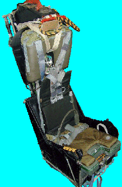
Mk. F-7
Early F-8 Crusaders were equipped with the Mk. F-5 seat which was good only at a speed of 115kts on the runway and so they were replaced with the upgraded Mk. F-7 seats once they were developed which gave performance to zero knots-zero altitude.
Among the upgrades, the hard parachute box replaced the earlier fabric containers which were vulnerable to sun damage as well as wear from use. The box is mounted resting on a saddle shaped fitting on the seat back under which the inertia reel straps protrude. The hard case is protected by a metal hood covering the back and surrounding the back edge of the parachute box. The harness setup is the standard American style with the harness individually fit to the crew and worn to the aircraft where it is attached to the risers and survival kit.
A key feature of the early Mk. F-7 family is the use of a mechanical initiator for the underseat rocket. The rocket uses a lanyard attached to the floor of the aircraft to ignite the rocket. The lanyard is stored in a spiral tray under the rocket and clips to a fitting on the floor of the cockpit. The lanyard is set to a length that initiates the rocket at the top of the catapult stroke. More information on the rocket can be found below in the commonality section.
One unique feature of the Mk. F-7 is the second handle on the headrest. On the left side of the headrest is a handle which allows the seat to be fired through the canopy if it fails to jettison.

|
| The pictures are not exactly to scale. |
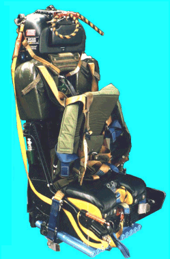
The underseat rocket is much like the rocket fitted to the Mk. F-7 and is described more in the commonality section below.
Other versions of the GQ-7(A) have been used for exported F-5 aircraft, and the NASA X-29 forward swept wing technology demonstrator.
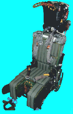
Mk. GRU-7(A)
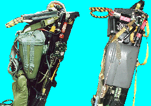
The Mk. GRU-7(A) seat is a late model Mk. 7 family member. It is the direct decendant of the GRU-5 seat used in the early A-6 Intruder aircraft. That seat became the GRU-7 seat (with many modifications), which was followed by the GRUEA-7 for the stretched EA-6 Prowler aircraft. Since it was a later design it shows the evolution of the seats from the earlier designs quite well. The F-14A required some other changes so its seat became the GRU-7(A). Features of the Mk. GRU-7(A) include a redesigned headrest and drogue container, a flatter, lower fiberglass parachute container, a survival kit with integral oxygen bottle, and an extended seat bucket shape. The underseat rocket is a gas initiated unit with a separate initiator actuated by a trip rod assembly and lanyard on the side of the drogue gun unit. The lower down parachute box slims down the area at the top of the seat to allow for better rearward visibility. A curved guard was added to protect the linkages of the timer release mechanism and the drogue gun unit as well as the rocket initiator.
Commonality
Underseat Rockets
Although the configuration of the underseat rockets varies, two of these seats have typical ones. The GRU-7(A) and GQ-7(A) seats shown use the standard late configuration. The configuration consists of a central manifold that has ports for several approxamately one inch diameter tubes of propellant, several nozzles (usually six in two groups of three), and an intiator. Also attached to the manifold is a extension lever or as it is also called, an adjusting arm. The underseat rocket on all of these seats are bolted to the seat bucket with a pair of bolts at the ends of the manifold, and connect via the adjusting arm to the main beam assembly cam follower groove. This allows the rocket to tilt slightly on the bolted axis to better align the center of thrust with the center of gravity (CG) of the seat/man mass. What this does is increases seat stability during the boost phase by keeping the seat/man mass balanced on the thrust. If it were not, the seat would get an induced tumbling movement that could possibly harm the aircrew riding the seat. The way it works is based on the seat bucket's position on the main beam assembly. The lower the bucket, the larger the person on the seat, hence the rocket would be tilted to a position where the center of gravity is expected to be for a large individual. The higher the seat bucket, the lighter the occupant is likely to be so the cam would cause the rocket to tilt to another position better for that CG.
The underseat rocket is responsible for one of the main reasons for the smaller branches of the Mk. 7 family tree. The six nozzles on the seat often are not symetric, with one or more nozzles being larger than the rest. Given the increase in thrust to one side from this, the seat tends to roll in the opposite direction. This effect is used in multi-place aircraft to provide seat separation during a sequenced ejection. For example, the GRU-7A Pilot seat rolls to the left side, and the GRU-7A MCO (Mission Control Officer or Radar Intercept Officer {RIO}) aft seat rolls to the right side. Thus there is a very minor difference between the seat versions in terms of the rocket bolt mounts with the larger nozzle being on the same side as a large bolt and bushing. In the EA-6B four place aircraft, there are three different rocket designs in use on the GRUEA-7 seats. (These are Pilot and ECMO-3 rolling left, ECMO-1 rolls right, and ECMO-2 has symetric nozzles for no roll.)
The Mk. F-7 seat uses a somewhat earlier design rocket, with some special issues to it.
This rocket does not have the tilt capability of the others, and is fixed in place by the two bolts and a pair of clamps forward on the tubes, near the front end of the seat. This is in pard due to the different weight distribution on the Mk. F-7 seat, which is more top heavy than other Mk. 7 seats. This keeps the C/G fairly far aft on the seat and minimizes the offset needed.
Earlier versions of the GQ-7(A) also had a simpler design underseat rocket. In one photo I have of an early GQ-7(A) the mechanical initiator lanyard was routed in an 'S' pattern lighly connected to the rocket tubes. This was replaced in later versions with the spiral mount.
Other Features
All three of these seats have face curtains and secondary handles, although the configuration of each varies. The seats also all use the same type of mechanisms as the Mk. 4 & Mk.5 seats do, such as the Timer Release Mechanism (TRM), Drogue Gun Unit (DGU), and catapult. The following descriptions are basic ones, and I recommend that the reader view the Mk. 4 & 5 Mechanisms page for details and animated gifs of their functions.
The Timer Release Mechanism (or Timer Release Unit) is a mechanical device on the upper right of the main beam assembly. It is actuated via a trip rod. An internal timer unit delays the release of the drogue parachute and restraints which hold the aircrew to the seat until a specified time has passed from the ejection seat beginning to move. The Drogue Gun unit on the upper left of the main beam assembly is used to deploy a pair of small drogue parachutes to slow the seat and stabilize it after ejection. It is also trip-rod acutuated, and contains a timer to fire the drogue slug at the appropriate time. The catapult unit is a set of three telescoping tubes, the outer most of which is bolted to the airframe and also contains a set of rails which interface with slipper units on the inside edges of the main beams. The innermost tube contains the primary catapult charge at the very top, along with the locking groove and gate which the top latch mechanism uses to retain the seat in the aircraft during negative G force maneuvers.
The seats are raised and lowered electronically via a motorized worm gear between the beams, in front of the catapult and behind the bucket. They also use leg garters for limb restraint, however the type of the garters varies somewhat between the seats.
