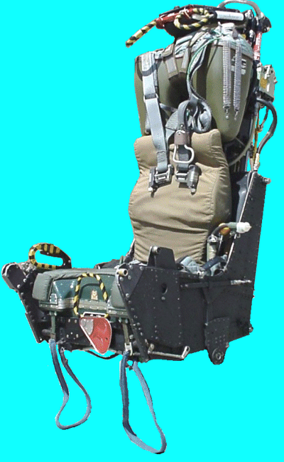
 The Martin-Baker Aircraft Co. Ltd (MBA) Mk. H-7 seat is one of the most manufactured ejection seats
in the world with some 11000 manufactured or modified to the Mk. H-7 standard from the earlier
Mk. H-5 seat. The H-7 is one of the most interesting seats in the MBA family due not only to its large number, but also due to its length of service, and the evolution which it displays. The seat systems are covered on this page on the USAF version of the H-7.
The main difference between the USAF H-7 and the USN H-7 is the survival kit and oxygen bottle. This seat is equipped with the USN survival kit with the internal oxygen bottle. The USAF CNU-111/P kit does not contain the oxygen bottle and uses a bottle mounted in the seat bucket. The associated REDAR hoses and communication lines from the survival kit are quite evident in these photos. In the top view, the hole in left thigh area of the seat kit padding to view the oxygen bottle pressure is also visible. Contrast the shape of the survival kit in the front view with the front view of a USAF H-7. Also note the location of the emergency oxygen atuation ring on the USN seat, and the USAF characteristic green ball on the side of the seat pan. This seat is complete with the SEWARS equipped Koch fittings on the parachute risers.
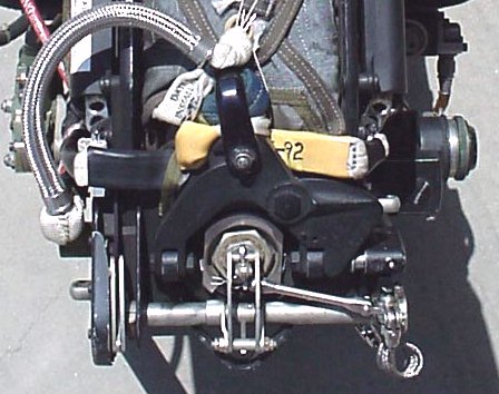
Of particular interest here is the photograph of the top of the seat which clearly shows the way the banana links and interdictor block are related. When either the face curtain or secondary firing handles are pulled, the torque tube across the rear of the main beam assembly at the top is rotated which fires the seat mounted initiator (located on the back of the seat, and not installed on this seat). This seat mounted initiator sends hot gas into the aircraft mounted canopy jettison system. This system electronically unlocks the canopies and used compressed gas to jettison them. The interdictor block is the unit at the back right side of the torque tube. A coiled wire lanyard from it is connected to the canopy so that when the canopy is jettisoned, the interdictor block is removed from the top of the seat. The bar from the interdictor block is connected to a pin which is acting as a physical interlock on the catapult sear at the center of the hexagonal firing mechanism, just under the banana links. This bar and pin are removed as part of the interdictor block assembly by the lanyard, which allows the torque bar to continue its movement under the power of the seat mounted initiator and remove the sear from the catapult initiator. From that point on, the seat functions the same as all other non-sequenced Martin-Baker seats. The primary catapult charge fires and begins to extend the catapult. The seat movement causes the trip-rods to remove the sears from the TRM on the right and the DGU on the left. The DGU trip-rod also has the lanyard for the underseat rocket initiator which is partially visible under the silver braided drogue extraction line.
Careful examination of the picture shows a pair of items that look similar to a pair of pull tabs from a soda can just aft of the cylinders on either side of the headrest. These are the ends of the face curtain restraint lines which feed through those tubes to the front of the headrest where the face curtain is stowed. The rear holes on these lines is held in place by a pair of cotter-pin like units attached to the yellow coated strap. This strap is attached to the main parachute withdrawal line. When the TRM timer runs out, the scissor shackle (the large black inverted 'V' shape across the seat back with its legs on either side of the catapult firing mechanism) is released by the removal of the pin barely visible poking through the black fitting just in front of the interdictor block. This allows the silver plunger to retract and the scissor to open at the apex ov the 'V' and release the drogue shackle. This then allows the drogues to pull the parachute withdrawal line out, along with the face curtain retaining pins. Also held by those pins, but not visible in this picture is the end of the parachute retaining straps. The withdrawal line pulls the pins from the parachute container flaps and withdraws the parachute. As the parachute retaining straps are released, two strong springs under the parachute box force the seat occupant and parachute away from the seat. Thanks to the anonymous collector who owns this seat, and has put up with my requests to take just one more picture many times!
Other Versions of the Martin-Baker Aircraft Phantom Seats are available on these pages:
| Front View |
| Left Side |
| 3/4 Left |
| Right Side |
| 3/4 Right |
| Rear view |
| View from above
showing the banana links and interdictor connection |
