The Ejection Site
F-4 Phantom II Martin-Baker Mk. H-7 Ejection Seat
 The Martin-Baker Aircraft Co. Ltd (MBA) Mk. H-7 seat is one of the most manufactured ejection seats
in the world with some 11000 manufactured or modified to the Mk. H-7 standard from the earlier
Mk. H-5 seat. The H-7 is one of the most interesting seats in the MBA family due not only to its large number, but also due to its length of service, and the evolution which it displays.
The Martin-Baker Aircraft Co. Ltd (MBA) Mk. H-7 seat is one of the most manufactured ejection seats
in the world with some 11000 manufactured or modified to the Mk. H-7 standard from the earlier
Mk. H-5 seat. The H-7 is one of the most interesting seats in the MBA family due not only to its large number, but also due to its length of service, and the evolution which it displays.
Due to the McDonnell-Douglas Phantom II entering service in the early 1960s, the seats originally fit to the production aircraft were Martin-Baker Mk. H-5 seats. These seats were rated at about 115kt on the runway. Their configuration varied significantly from the Mk. H-7 in that the main parachute container was a soft pack, and was held in a hooded backrest similarly to the Mk. F-5 and Mk. F-7 seat used in the F-8 Crusader. The seat bucket was similar to the later Mk. H-7 versions. Over the years, the parachute container was changed to the hard fiberglass container, and the hood was deleted. The rocket pack was added to the seat, bringing it up to the Mk. 7 family specifications which lowered the speed required on the runway to zero knots. The original Mk. 51 underseat rocket utilized a mechanical initiator with a lanyard attached directly to the rocket. Later on the rocket was changed to the Mk. 92 gas initiated rocket, which enabled the lanyard to be moved to the underseat Rocket Initiator as seen below. These changes, and some other smaller ones, made the Mk. H-7 a very good example of seat evolution.
One unique feature of the Mk. H-7 family (which includes four main variants; USAF Pilot, USAF WSO, USN Pilot, USN RIO) is that the seat buckets are designed to be removed in the aircraft for maintanance. Then, the main beam assembly is unlatched from the catapult and raised a short distance to a point where it can be tilted forward via slots in the catapult rails and removed without removing the canopy of the aircraft.
Description
Bolted to the upper section of the main beam assembly is the headrest which doubles as the housing for the drogue
chute, and the mounting location for the upper ejection handles.
This seat utilizes a large fiberglass box (dark green) which is
on the order of 19 inches wide, 14.5 inches high and about 6-7 inches max
thickness. It has a bulging nylon cover at the top which protects the
packed chute. It has a concave front with a upside down "U"
shaped cutaway in the center. This slot rises some 8.5 inches from the
base and the container is hung from the slot on a matching saddle shaped protrusion on
the seat back. A pair of springs are placed between the parachute box and the seat back during rigging of the seat, and are retained with the pack by a pair of pack retention bands which are attached from the saddle area to the point on the headrest where the face curtain is also attached. The pack restraining bands and the face curtain are retained in place by a pair of pins akin to cotter pins. These pins are attached to the main parachute withdrawal line and pulled by the lines when the scissor shackle on the top of the seat is released by the action of the Timer Release Mechanism (TRM) The
The Drogue chute container is also a fiberglass material with a
heavy 4-flap nylon cover. Only the edge of the fiberglass is visible
as the container is form fit to the receptical slot in the top of the
main beam assembly. (See OV-1
MB MK. J5D Main Beam for an example of this construction.)
Flanking the top of the main beam assembly
are the TRM and Drogue Gun. The TRM (Timer-Release-Mechanism) is a unit
that is tripped by a trip-rod connected to the cockpit bulkhead as the
seat rises up the rails. When activated, a timer mechanism counts down
for a few short seconds allowing the drogue chute to slow and stabilize
the seat, prior to seat seperation. The timer is inhibited by a barostat
assembly (the cylinder protruding from the TRM) if the seat is above
15000 feet. When the TRM completes its timer stroke, a rod is retracted from the top,
and extends out the bottom to depress a lever. This lever moves a bellcrank mechanism to rotate a pair of metal rods that extend vertically into the seat bucket, and also to release the inertia reel latches to release the seat occupant. The rods release the leg restraints and the survival kit latches as well as the seat belt release on the USAF seat.
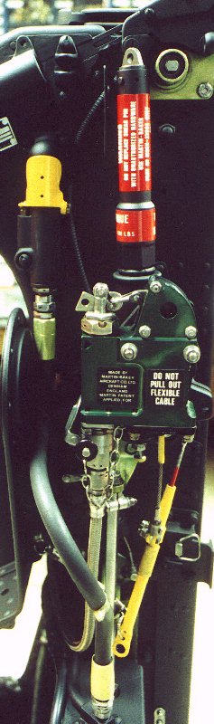
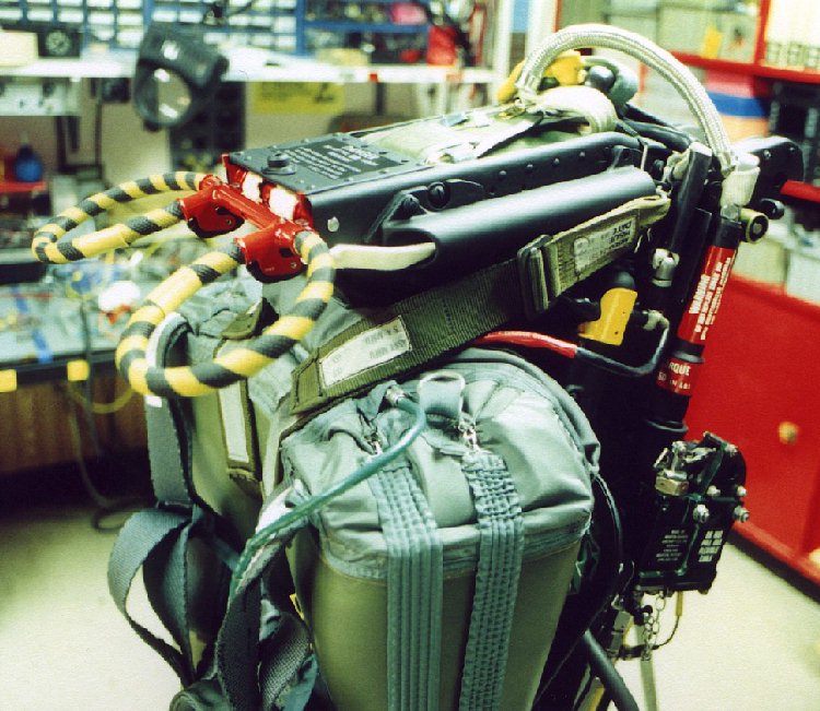
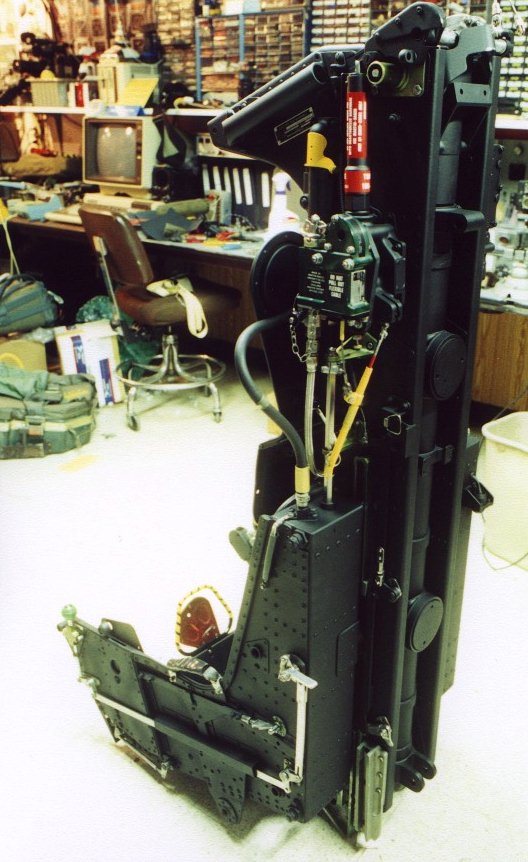
 The Drogue Gun Unit (DGU) fires approxamately 3/4 of a second after the seat begins moving
up the rails. It fires a metal slug with enough energy to drag the smaller of the duplex drogue parachutes out of its pack and allow it to deploy. The picture to the right shows the silver end of the drogue slug without the drogue withdrawal line attached. The barrel of the DGU is the thinner red labled cylinder at the top. The thicker area is the chamber area of the barrel where the charge is installed. The green anodized unit attached to the reciever/timer portion of the DGU is the underseat Rocket Initiator. This unit uses a lanyard attached to the yellow trip-rod which pulls the sear from the DGU. This trip-rod is attached to the cockpit via a crossbeam unit bolted to the catapult's outer tube. When the seat begins to move up the rails the trip-rod withdraws the sear from the DGU and begins to unspool the lanyard from the rear section of the Rocket Initiator. When the catapult nears the end of the stroke, and the lanyard reaches its end, it pulls the sear from the Rocket Initiator via a lever in the top, curved section of the unit. This fires a cartridge in the Rocket Initiator and sends hot gas via the flexable hose attached to the base of the unit down to the underseat rocket firing mechanism.
The Drogue Gun Unit (DGU) fires approxamately 3/4 of a second after the seat begins moving
up the rails. It fires a metal slug with enough energy to drag the smaller of the duplex drogue parachutes out of its pack and allow it to deploy. The picture to the right shows the silver end of the drogue slug without the drogue withdrawal line attached. The barrel of the DGU is the thinner red labled cylinder at the top. The thicker area is the chamber area of the barrel where the charge is installed. The green anodized unit attached to the reciever/timer portion of the DGU is the underseat Rocket Initiator. This unit uses a lanyard attached to the yellow trip-rod which pulls the sear from the DGU. This trip-rod is attached to the cockpit via a crossbeam unit bolted to the catapult's outer tube. When the seat begins to move up the rails the trip-rod withdraws the sear from the DGU and begins to unspool the lanyard from the rear section of the Rocket Initiator. When the catapult nears the end of the stroke, and the lanyard reaches its end, it pulls the sear from the Rocket Initiator via a lever in the top, curved section of the unit. This fires a cartridge in the Rocket Initiator and sends hot gas via the flexable hose attached to the base of the unit down to the underseat rocket firing mechanism.
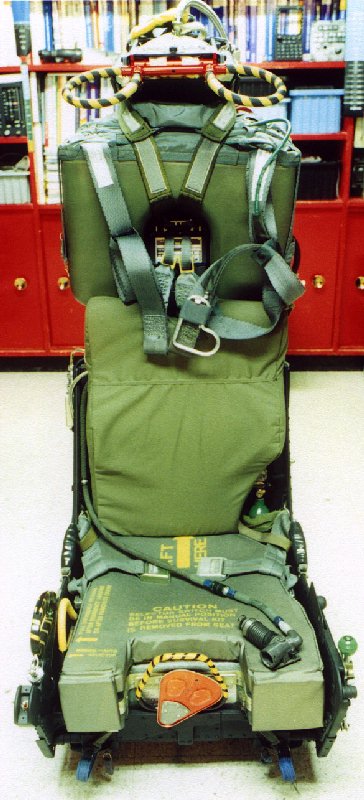
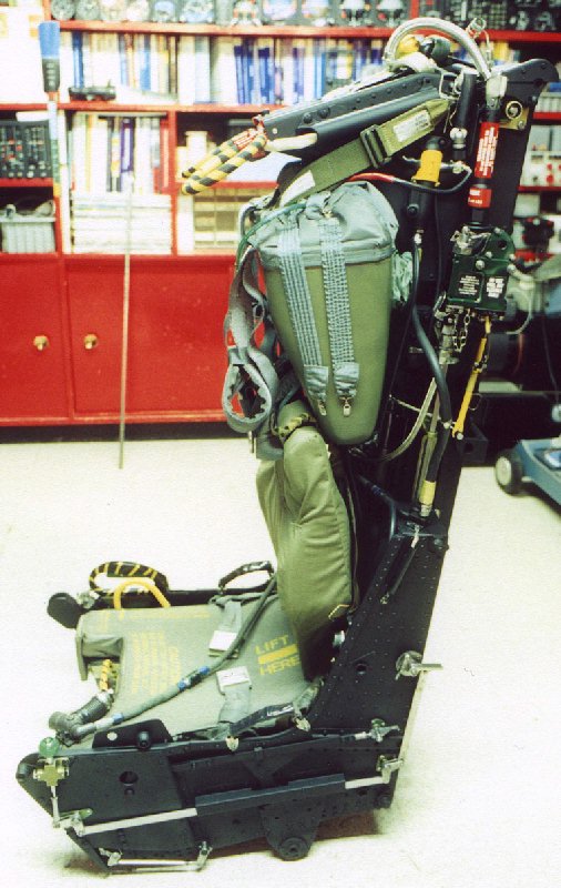
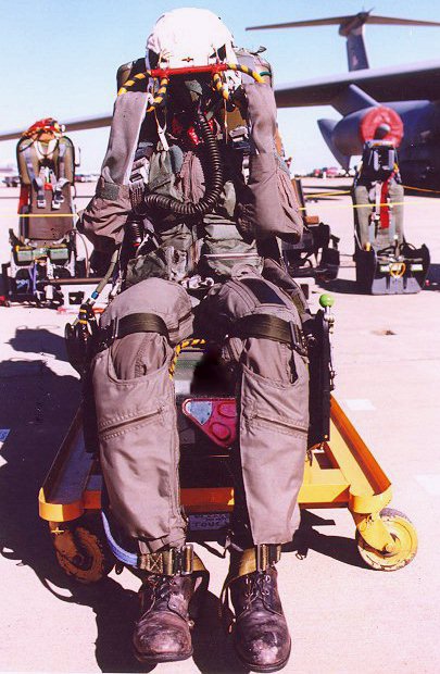
The location of the oxygen bottle is a key difference with the Mk. H-7 used in the US Navy and Marine Corp aircraft. The USN and USMC include the oxygen bottle in the survival kit. On this USAF seat, the bottle is visible behind the cushion in the front view. In that photo you can also see the emergency oxygen line connected to a CRU-60/P unit lying on the seat cushion. The CRU-60/P unit connects the aircraft oxygen, the seat mounted emergency oxygen, and the crewman's oxygen mask. On the left of the seat bucket in this photo the green ball (called an 'apple') manual actuator for the emergency oxygen supply is visible along with its mechanical linkage. Normally on the USAF version of the seat there is a separate lap belt, but this seat does not have it fitted yet.
The seat pictured here has been restored by Matt Wietlispach
and will be replacing the F-100D seat in his amazing simulator. Thanks Matt for the pictures!
Other Versions of the Martin-Baker Aircraft Phantom Seats are available on these pages:
The following pictures show a Mk. H-7AF after restoration.
Note: The lap belt and parachute riser fittings (Koch with SEWARS)
have not been installed yet.
(A USN seat with the risers complete can be seen here) |
|---|
| Front View |
| Left side |
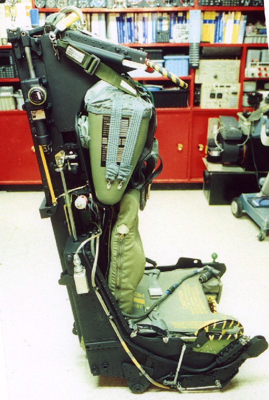
| Right side |
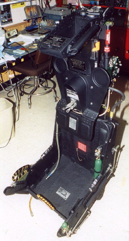
| Bare seat |
| Headrest area from the left |
| Closeup of the Drogue Gun Unit and Rocket Initiator |
Left side from the rear
Note the bracket for the seat mounted initiator
at the top of the catapult |
|
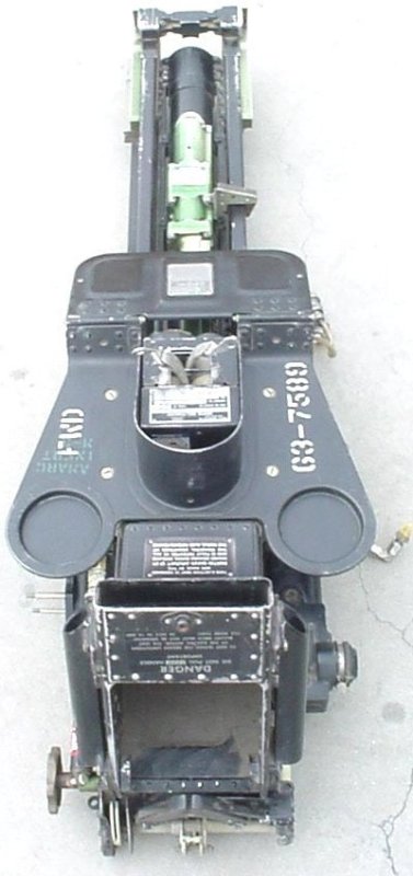
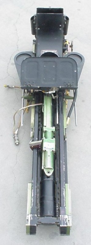
The following views of an anonymous friend's Mk. H-7AF
Main Beam Assembly (MBA) shows the relationship of several of the parts.
Note: the catapult tube is still installed. |
|---|
| From the top |
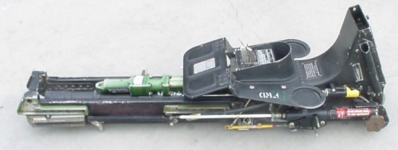
Left side note the top latch wheel,
drogue gun with mount
for the rocket initiator, and the green channels for the seat bucket. The bottommost channel
at a slight angle is the cam track for the underseat rocket. |
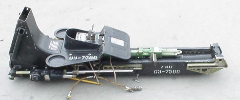
Right side Note the TRM with the rods extended, the and the green seat
bucket height adjust motor |
From the bottom Shows the seat height adjust motor with the seat back slide cover
raised. The two square steel rods extending downwards from the green
braces on either side of the MBA are rotated by a bellcrank assembly
to release the seat restraints at seat separation. |
|
| The following are a few diagrams from the Flight Manual for an F-4E |
|---|
| Phantom Seat, Left side |
| Phantom Seat, Right side |
| Phantom Seat, Kit |
| Phantom Seat, Top |
| Phantom Seat, Top Left |
Phantom Seat, with manikin pulling face curtain
Note the M-B Mk F-7 behind to the left, and the Escapac to the right rear |
 The Drogue Gun Unit (DGU) fires approxamately 3/4 of a second after the seat begins moving
up the rails. It fires a metal slug with enough energy to drag the smaller of the duplex drogue parachutes out of its pack and allow it to deploy. The picture to the right shows the silver end of the drogue slug without the drogue withdrawal line attached. The barrel of the DGU is the thinner red labled cylinder at the top. The thicker area is the chamber area of the barrel where the charge is installed. The green anodized unit attached to the reciever/timer portion of the DGU is the underseat Rocket Initiator. This unit uses a lanyard attached to the yellow trip-rod which pulls the sear from the DGU. This trip-rod is attached to the cockpit via a crossbeam unit bolted to the catapult's outer tube. When the seat begins to move up the rails the trip-rod withdraws the sear from the DGU and begins to unspool the lanyard from the rear section of the Rocket Initiator. When the catapult nears the end of the stroke, and the lanyard reaches its end, it pulls the sear from the Rocket Initiator via a lever in the top, curved section of the unit. This fires a cartridge in the Rocket Initiator and sends hot gas via the flexable hose attached to the base of the unit down to the underseat rocket firing mechanism.
The Drogue Gun Unit (DGU) fires approxamately 3/4 of a second after the seat begins moving
up the rails. It fires a metal slug with enough energy to drag the smaller of the duplex drogue parachutes out of its pack and allow it to deploy. The picture to the right shows the silver end of the drogue slug without the drogue withdrawal line attached. The barrel of the DGU is the thinner red labled cylinder at the top. The thicker area is the chamber area of the barrel where the charge is installed. The green anodized unit attached to the reciever/timer portion of the DGU is the underseat Rocket Initiator. This unit uses a lanyard attached to the yellow trip-rod which pulls the sear from the DGU. This trip-rod is attached to the cockpit via a crossbeam unit bolted to the catapult's outer tube. When the seat begins to move up the rails the trip-rod withdraws the sear from the DGU and begins to unspool the lanyard from the rear section of the Rocket Initiator. When the catapult nears the end of the stroke, and the lanyard reaches its end, it pulls the sear from the Rocket Initiator via a lever in the top, curved section of the unit. This fires a cartridge in the Rocket Initiator and sends hot gas via the flexable hose attached to the base of the unit down to the underseat rocket firing mechanism.