When it's completed, the simulator will be completely enclosed with a 31"
computer monitor in front of the main instrument panel. It will take several
computers to run the simulator including a Pentium II 233 to run the simulation
software and less powerful computers to run instrument subsystems
and displays.
UPDATE-
 In the year since this was written, Matt has not been idle. He has acquired many
new parts, reverse engineered them and installed several new ones. The sim is now
outfitted with a 35inch monitor and has been tested, prior to it being shut down
again for yet more modifications. The MFDs are from F-16s and the HUD is from
an A-7.
In the year since this was written, Matt has not been idle. He has acquired many
new parts, reverse engineered them and installed several new ones. The sim is now
outfitted with a 35inch monitor and has been tested, prior to it being shut down
again for yet more modifications. The MFDs are from F-16s and the HUD is from
an A-7.
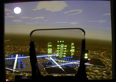
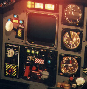
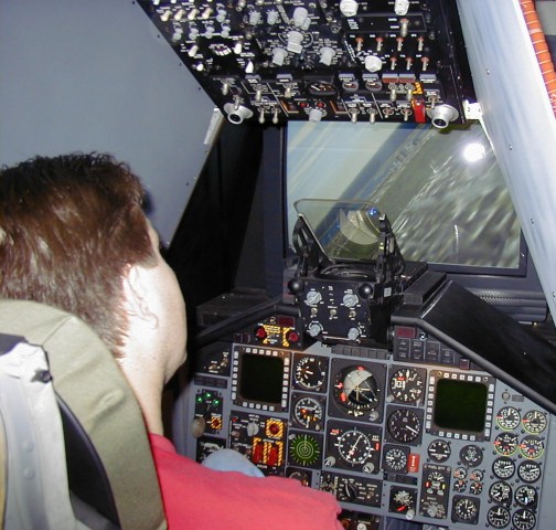 Matt's work finally begins to pay off, as seen in these photos of the simulator in
action. The A-7 HUD is now active and slaved to the computer via the EPIC card as are
several of the instruments. The most obvious of which is the Attitude Direction Indicator
(ADI) which is the round ball in the center. The ADI is colored to represent the sky (grey)
and the ground (black) and tilts to show the angle of bank of the aircraft. The picture
clearly shows the horizons matching.
Matt's work finally begins to pay off, as seen in these photos of the simulator in
action. The A-7 HUD is now active and slaved to the computer via the EPIC card as are
several of the instruments. The most obvious of which is the Attitude Direction Indicator
(ADI) which is the round ball in the center. The ADI is colored to represent the sky (grey)
and the ground (black) and tilts to show the angle of bank of the aircraft. The picture
clearly shows the horizons matching.
 In Matt's words, here is the state of the machine:
"! The throttles, rudder pedals,
control stick, gear lever and engine start/fuel cutoff switches are all
interfaced to the computer via the EPIC card. The HUD is now fully
operational and provides real-time lag-free data directly on the HUD glass.
The primary instruments such as the ADI, Altimeter, IAS, V/S, and HSI are all
operational! Instruments accurately track data shown in the HUD!
Improvements are being made to all systems as development continues."
In Matt's words, here is the state of the machine:
"! The throttles, rudder pedals,
control stick, gear lever and engine start/fuel cutoff switches are all
interfaced to the computer via the EPIC card. The HUD is now fully
operational and provides real-time lag-free data directly on the HUD glass.
The primary instruments such as the ADI, Altimeter, IAS, V/S, and HSI are all
operational! Instruments accurately track data shown in the HUD!
Improvements are being made to all systems as development continues."
Overall, a fantastic achievement!
This page has been accessed
 times since November 06, 1997
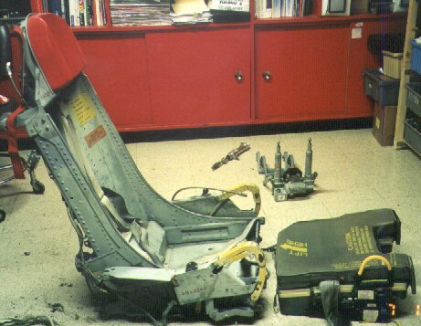 This picture shows the F-100 seat as it arrived from Mojave, CA. It was dirty, but
serviceable. The seat pack/survival kit to the right of the seat
is a CNU/111P from a Martin Baker F4 Phantom ejection seat. Miraculously , it
fit perfectly into the pan of the F-100 seat. I will install a large subwoofer in the
F4 seat pack to enhance the simulation experience. In the
background you can see the 28VDC two arm seat actuator motor. I had to rebuild
it to get it to work, but the result as an actuator with a 600lb lift
and push capacity. It could easily lift the 85lb seat and me times three!
This picture shows the F-100 seat as it arrived from Mojave, CA. It was dirty, but
serviceable. The seat pack/survival kit to the right of the seat
is a CNU/111P from a Martin Baker F4 Phantom ejection seat. Miraculously , it
fit perfectly into the pan of the F-100 seat. I will install a large subwoofer in the
F4 seat pack to enhance the simulation experience. In the
background you can see the 28VDC two arm seat actuator motor. I had to rebuild
it to get it to work, but the result as an actuator with a 600lb lift
and push capacity. It could easily lift the 85lb seat and me times three!
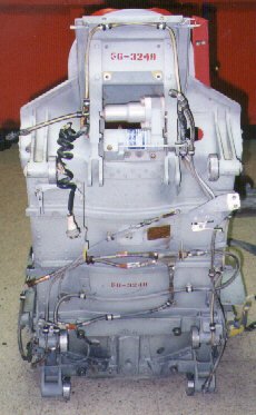
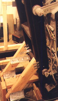
 The picture on the left shows the bottom of the F-100 seat with several bundles of old
rope removed. These bundles were packed behind a retention
assembly that was designed to release during the ejection process. Steel cables
attached to one end of the rope assembly were affixed to the airframe.
Upon ejection, the anchored ropes were pulled through a series of spools
that provided enough friction to help stabilize the seat as it ejected off of
its track and away from the aircraft. This was part of the DART system intended to reduce
tumbling during ejection. At least that's what the decals
revealed. There were metal foot rests that hung down from the tube seen at
the top of the seat (I removed them.) The spring leading to the round apparatus
on the right locked the eject handles in the up position when pulled. A metal flap
to the right and behind that apparatus is pulled to release the lock and return the
handles to their lowered position.
The picture on the left shows the bottom of the F-100 seat with several bundles of old
rope removed. These bundles were packed behind a retention
assembly that was designed to release during the ejection process. Steel cables
attached to one end of the rope assembly were affixed to the airframe.
Upon ejection, the anchored ropes were pulled through a series of spools
that provided enough friction to help stabilize the seat as it ejected off of
its track and away from the aircraft. This was part of the DART system intended to reduce
tumbling during ejection. At least that's what the decals
revealed. There were metal foot rests that hung down from the tube seen at
the top of the seat (I removed them.) The spring leading to the round apparatus
on the right locked the eject handles in the up position when pulled. A metal flap
to the right and behind that apparatus is pulled to release the lock and return the
handles to their lowered position.
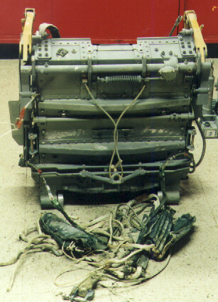
 The rear of the F-100 seat consists of a variety of high pressure lines designed
to carry hot discharge gasses to various assemblies during the ejection process.
One destination for the pressure lines was the shoulder
harness roller assembly which locked upon ejection. The hanging coiled electric
cord was connected to the seat actuator assembly that attached to
the chair via the two lift points to the right of it. The rollers on each
side revealed the seat was designed to rest solely on tracks that it slid onto in
the cockpit. The data plate told me that North American Rockwell built the
chair in 1956 for F-100 #56-3248. The electric switch used for raising and
lowering the seat is located on the left arm rest and the electric wires to the
actuator traveled up the back of the seat on the right.
The rear of the F-100 seat consists of a variety of high pressure lines designed
to carry hot discharge gasses to various assemblies during the ejection process.
One destination for the pressure lines was the shoulder
harness roller assembly which locked upon ejection. The hanging coiled electric
cord was connected to the seat actuator assembly that attached to
the chair via the two lift points to the right of it. The rollers on each
side revealed the seat was designed to rest solely on tracks that it slid onto in
the cockpit. The data plate told me that North American Rockwell built the
chair in 1956 for F-100 #56-3248. The electric switch used for raising and
lowering the seat is located on the left arm rest and the electric wires to the
actuator traveled up the back of the seat on the right.
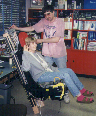 After making the electric seat actuator operable, I constructed a seat track
frame out of 2x4s and metal brackets. The tracks themselves were simply
steel 'L' brackets affixed to the wooden frame. The actuator rests on top of
the frame and is able to lift and lower the chair about 6 inches. To check
the motor, I enlisted the help of my wife Janet who, after a little coaxing,
agreed to be the chair's first guinea pig. The actuator had no trouble lifting
her and the seat. Once the frame was mounted in the simulator, it
had no trouble lifting me either. With a load capacity of 600lbs the actuator
motor soaked up almost 20 AMPS of 28VDC power, so I had to construct
a special bank of eight 3 amp transformers and rectifiers to power it.
After making the electric seat actuator operable, I constructed a seat track
frame out of 2x4s and metal brackets. The tracks themselves were simply
steel 'L' brackets affixed to the wooden frame. The actuator rests on top of
the frame and is able to lift and lower the chair about 6 inches. To check
the motor, I enlisted the help of my wife Janet who, after a little coaxing,
agreed to be the chair's first guinea pig. The actuator had no trouble lifting
her and the seat. Once the frame was mounted in the simulator, it
had no trouble lifting me either. With a load capacity of 600lbs the actuator
motor soaked up almost 20 AMPS of 28VDC power, so I had to construct
a special bank of eight 3 amp transformers and rectifiers to power it.
 The next challenge was to mount the seat and track frame in the simulator frame.
I had to get the frame height just right to make sure the seat bottom
rested on the floorboards and the angle right so the seat pan was level with
the frame. Also, it was essential to center it correctly since I had to build
control panel consoles to the left and right of the seat. I anchored
the seat track frame at numerous places onto the simulator frame since
I wasn't sure where all the stress points were. I figured overbuilding this
part was important since I didn't know who would sit in the seat in the
future and how heavy they might be. When finished I was pleased to find the
seat didn't 'wobble' in its tracks and the motion up and down was smooth.
When making the consoles on either side of the seat I had to be sure to
allow enough room to easily grasp around the ejection handles and release trigger.
The next challenge was to mount the seat and track frame in the simulator frame.
I had to get the frame height just right to make sure the seat bottom
rested on the floorboards and the angle right so the seat pan was level with
the frame. Also, it was essential to center it correctly since I had to build
control panel consoles to the left and right of the seat. I anchored
the seat track frame at numerous places onto the simulator frame since
I wasn't sure where all the stress points were. I figured overbuilding this
part was important since I didn't know who would sit in the seat in the
future and how heavy they might be. When finished I was pleased to find the
seat didn't 'wobble' in its tracks and the motion up and down was smooth.
When making the consoles on either side of the seat I had to be sure to
allow enough room to easily grasp around the ejection handles and release trigger.
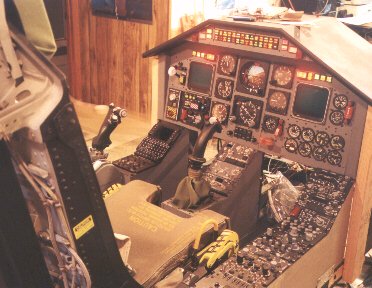
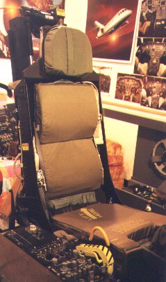 Here's a front shot of the F100 seat in the sim. The back cushions were two "Personnel
Lowering Devices" that were obvioulsy out of some ejection system since they were
designed with an integral cushion along with the bundled nylon cords.
Here's a front shot of the F100 seat in the sim. The back cushions were two "Personnel
Lowering Devices" that were obvioulsy out of some ejection system since they were
designed with an integral cushion along with the bundled nylon cords.
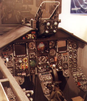
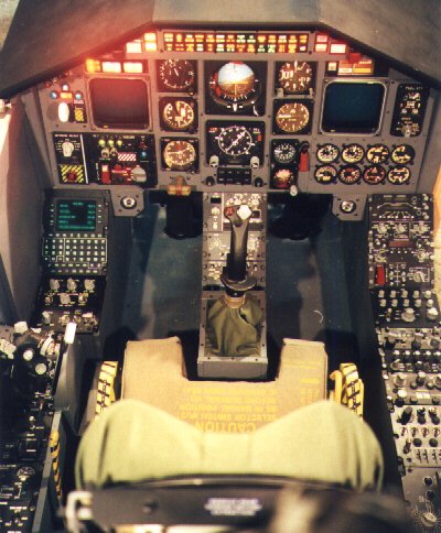 With the seat in place, I adjusted the depth of the rudder pedals so that I
was comfortable. I'm 6ft tall and didn't want my knees in my chest so I put
them further back than they really would be in an actual aircraft. I placed
the throttle and control assemblies around the seat in places where they were
comfortable and unobstructed. The console to the right contains the radio
communication and navigation equipment such as HF, V/UHF, TACAN, ADF, IFF ,
ICS and secure voice crypto controls. Behind the throttle quadrant on the
left contains the engine start panel, oxygen regulator, autopilot engage and
trim panel, and air conditioning panel. The front panel contains the typical
flight, navigation and engine instruments. The two circular objects protruding
on the corner of the leg wells are typical air vent nipples common
in airliners.
With the seat in place, I adjusted the depth of the rudder pedals so that I
was comfortable. I'm 6ft tall and didn't want my knees in my chest so I put
them further back than they really would be in an actual aircraft. I placed
the throttle and control assemblies around the seat in places where they were
comfortable and unobstructed. The console to the right contains the radio
communication and navigation equipment such as HF, V/UHF, TACAN, ADF, IFF ,
ICS and secure voice crypto controls. Behind the throttle quadrant on the
left contains the engine start panel, oxygen regulator, autopilot engage and
trim panel, and air conditioning panel. The front panel contains the typical
flight, navigation and engine instruments. The two circular objects protruding
on the corner of the leg wells are typical air vent nipples common
in airliners.
 The left hand of the front panel contains the following:
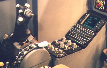 This picture depicts an authentic F-16 throttle grip mounted to an F-105 throttle
quadrant. The mechanics of the quadrant provides for an excellent
feel even though the F-16 grip is mounted vertically as opposed to horizontally
as it is was meant to. The quadrant also has a built in flap
lever which was very convenient. In front of the quadrant is the interior
and exterior lighting panels and in front of that is the flight management
system control/display unit. Like all other aircraft panels, the control/display
unit employs backlighting to illuminate all lettering. This
panel was designed to illuminate lettering with night-vision compatible green.
This picture depicts an authentic F-16 throttle grip mounted to an F-105 throttle
quadrant. The mechanics of the quadrant provides for an excellent
feel even though the F-16 grip is mounted vertically as opposed to horizontally
as it is was meant to. The quadrant also has a built in flap
lever which was very convenient. In front of the quadrant is the interior
and exterior lighting panels and in front of that is the flight management
system control/display unit. Like all other aircraft panels, the control/display
unit employs backlighting to illuminate all lettering. This
panel was designed to illuminate lettering with night-vision compatible green.
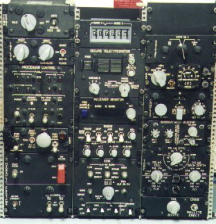 While it will be a while before I get to this point, the panels on the right
will be mounted above the ejection seat in a slidable shell-type roof. Just
like the panels in the side consoles, these are all 5.75" wide and interchangeable.
The twist lock dzus fittings on the panel corners make shuffling panels a breeze and
I won't know for some time where I will permanently have all panels arranged. Some
of the panels here control such things as electronic countermeasures, fuel dump,
compass setting, sonorbuoy audio monitoring, torpedo drop, shrike and walleye
volume and many other things. The dzus rails the panels are mounted on came
from a salvaged overhead panel.
While it will be a while before I get to this point, the panels on the right
will be mounted above the ejection seat in a slidable shell-type roof. Just
like the panels in the side consoles, these are all 5.75" wide and interchangeable.
The twist lock dzus fittings on the panel corners make shuffling panels a breeze and
I won't know for some time where I will permanently have all panels arranged. Some
of the panels here control such things as electronic countermeasures, fuel dump,
compass setting, sonorbuoy audio monitoring, torpedo drop, shrike and walleye
volume and many other things. The dzus rails the panels are mounted on came
from a salvaged overhead panel.