The Ejection Site
Ejection Seat Propulsion and Stability
Although these are very different topics, a discussion of either one is not complete
without the discussing the second. Early seat designers were mainly concerned
with getting the aircrew safely away from the aircraft, but even in the very
early days it was clear that the same effects that prevented the crew from
manually bailing out of many aircraft would effect the seated occupant. The
wind-blast effect was one of the main reasons that ejection seats were developed
in the first place. In the thirties it became apparent that at the higher speeds
that aircraft were travelling some crewmembers were having difficulty even
opening the canopy or hatch, let alone managing to climb out into the wind. This
was later more apparent to most of the air forces utilizing higher performance
craft. Not only was it difficult to climb out, but also the crewmember had the
risk of striking portions of the aircraft. Even if that did not occur, the
crewman might receive injuries as they tumbled out of control at a relatively
high speed. Many crew were lost to these kinds of incidents, and the
investigators realized that as ejection seats were developed stability would
have to be a factor.
As they worked to develop the ejection seats, most of the diverse teams working
on the problem came to similar conclusions. First of all the seat had to exit
the aircraft with enough speed to clear the empennage at the highest expected
speed. Second, the crewman had to be able to withstand not only the force of the
ejection charge, but also the dynamic force or 'Q' of the wind. In Germany, the
Heinkel Schludersitz designs incorporated a set of footrest bars that the
crewman was intended to place his feet on prior to ejection. This would place
his knees and lower legs in a position where they would clear the instrument
panel and the hatch through which he would eject. (This is referred to as the
ejection path). Secondly, the footrests would keep his body in a smaller frontal
area and hopefully prevent the legs from flailing in the wind.
Martin-Baker Aircraft used similar footrests and took this design one step
further by utilizing an overhead ejection handle, with a face curtain, to give
the crewman a method of keeping his arms more controlled. The face curtain gave
some protection to the face, and the overhead reach tended to help the crewman
straighten his back. SAAB in Sweden used a set of straps at each shoulder, which
accomplished the same thing. This was an important consideration as the force of
the seat firing was capable of injuring a crewman when they ejected.
Early German designs utilized various schemes to propel the seat and man
together out of the fuselage. Some of them included compressed air, elastic
bands, and of course pyrotechnic cartridges. The elastic bands and spring
systems were dangerous to rig, and were not reliable in the amount of force they
would produce. Compressed gas was a viable system, and was used in some
prototype and production aircraft. It was limited, however, in the maximum
amount of force it could provide without causing an injury. This made it
unsuitable for the higher performance aircraft, which would require a more
powerful boost to clear the tail and other obstructions aft of the cockpit at
the higher speeds. The Germans switched to a cartridge system which, by careful
selection of the propellant used, allowed for a more gentle (relatively)
ejection stroke.
There are two aspects of the initial catapult stroke which are potentially
injurious. One is of course the maximum force exerted, usually referred to in
the G-force experienced by the average seat occupant. Since in the co-ordinate
system used in most countries the vertical direction is the Z axis, this is a
positive-Z G-force, or +Gz for short. The second aspect is the onset rate of the
+Gz expressed in G per second. This is the more tricky one as the human body is
capable of astounding resilience when pushed, yet the concept of a seat that
provides a +14 Gz ejection causing an injury while a +16Gz jolt from another
seat does not is non-intuitive. The difference would likely be in the onset
rate. If the peak Gz force is reached in the first example at a much higher
rate, for example in 1/100th of a second that would translate to a 1400 GPS
onset rate. The latter seat might take twice as long to reach maximum force so
that 1/50th second at 16Gz translates to 800 GPS. This took much experimentation
to develop reasonable safe rates for both maximum Gz and GPS.
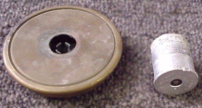
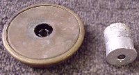 Martin-Baker Aircraft developed a multi-stage, telescoping catapult that uses a
primary cartridge at the top to begin seat movement. As the gas from this
cartridge expands inside the inner tube it forces the inner tube upwards,
driving the seat/man upward with a relatively low onset rate. As momentum builds
while the seat rises, ports in the outer tube of the catapult gun are uncovered
as the inner tube slid by. This allows the hot gas to enter the secondary charge
and ignite it. The additional gas pressure generated accelerates the extension
of the tubes and thus increases the speed of the seat/man mass. Since this
acceleration has been delayed, the onset rate is kept in reasonable bounds.
The photo to the right shows a secondary charge cartridge to the left of a primary catapult cartridge.
Martin-Baker Aircraft developed a multi-stage, telescoping catapult that uses a
primary cartridge at the top to begin seat movement. As the gas from this
cartridge expands inside the inner tube it forces the inner tube upwards,
driving the seat/man upward with a relatively low onset rate. As momentum builds
while the seat rises, ports in the outer tube of the catapult gun are uncovered
as the inner tube slid by. This allows the hot gas to enter the secondary charge
and ignite it. The additional gas pressure generated accelerates the extension
of the tubes and thus increases the speed of the seat/man mass. Since this
acceleration has been delayed, the onset rate is kept in reasonable bounds.
The photo to the right shows a secondary charge cartridge to the left of a primary catapult cartridge.
Later, as it became apparent that the seats were saving aircrew at altitude, but
the limited safe ejection envelope did not extend down to the ground where many
accidents occurred, the seat engineers went back to work on improving the seat
propulsion systems. This led Martin-Baker Aircraft to add a third tube to allow
for further expansion and lengthen the catapult stroke. At the same time they
added more secondary cartridges to increase the staggered gas pressure. These
changes increased the ability of the seat to clear the empennage, and allowed
for ejection at altitudes as low as runway level. There were several
modifications to other mechanisms on the seat to allow for safe ejection on the
runway. Once these were accomplished, the Martin-Baker Aircraft seats were much
in demand by the Naval Aviation branches of several militaries.
SAAB in Sweden developed a two-tube catapult system using a central gas
generator to drive the seat up the rails in their early seats. This was after
their experimentation showed that springs, elastic, and compressed air were not
suitable for various reasons. A similar dual catapult system was later adopted
for use in the Stencel Aero Engineering S-III-S ejection seat family. This system has dual
catapult tubes linked together with a single gas generator. Later
still, the Martin-Baker Aircraft Mk. 15 and Mk. 16 family began to use a similar
system. These changes were done as the catapult tubes become part of the
structure of the seat, which lightens the seat as well as making it less thick
front to back.
In the United States early development was based on captured German ejection seats. Due to the lack of suitable cartridges the captured catapults were never used successfully. The Wright Air Development Center laboratory designed a replacement catapult, which later was standardized as the M5 catapult. These catapults were two concentric tubes with a single cartridge, and were not generally suitable
for use below about 500 feet. Once the Martin-Baker seat was demonstrated, the
USN changed to their seats. The USAF remained using American made seats for the
most part.
Seat stability enters the picture here as the seats were being used at lower
speeds and altitudes than they were originally designed for. Due to the ejection
force on all seat designs being aligned with the back of the seat/man mass, well
behind the center of gravity, the seats had a pronounced forward roll that would
occur on exit from the aircraft. At speed, the air blast would tend to counter
this, and the seat would either not tip at all, or tip slowly either forward or
backward depending on various forces that were involved.
These kinds of actions led to the crewman being exposed to wind forces from
unpredictable directions, which could lead to injuries from flailing limbs. Seat
designers then had to take that into consideration with additional safety
devices such as arm restraints and other items.
 Soon after this, seat designers were presented with the challenge of expanding
the ejection envelope still further to include even slower ejections on the
ground, as well as to encompass higher sink rates at lower altitudes. To do this
would require more propulsive force, as well as a method of preventing the loss
of some of the altitude gained by the aforementioned tumbling. Martin-Baker
Aircraft designed and tested the underseat rocket. This rocket package is made
of a manifold to which is joined a set of tubes containing rocket propellant, an
igniter tube, and a set of rocket nozzles. See the photo to the right.
Soon after this, seat designers were presented with the challenge of expanding
the ejection envelope still further to include even slower ejections on the
ground, as well as to encompass higher sink rates at lower altitudes. To do this
would require more propulsive force, as well as a method of preventing the loss
of some of the altitude gained by the aforementioned tumbling. Martin-Baker
Aircraft designed and tested the underseat rocket. This rocket package is made
of a manifold to which is joined a set of tubes containing rocket propellant, an
igniter tube, and a set of rocket nozzles. See the photo to the right.
This design had an advantage as the manifold was mounted nearly directly under
the nominal seat/man center of gravity, which would allow for most of the thrust
to be used for upward motion as opposed to the other design which had a distinct
forward component to the thrust vector. This alignment with the center of thrust
and the center of gravity (CG) was not always exact, and would therefore allow
for thrust induced tumbling. The CG area or egg is calculated for each seat/man configuration
and appears to be a roughly egg shaped area which is aligned at an angle with the
smaller, lighter occupant at one end, and the heavier occupant at the other end.
In many European seats, the rocket is mounted by a pair
of pivots on each side of the seat pan. On one side of the pan is a control dial
which the crewman sets as they strap in to their total person/personal equipment
weight. This, by means of a threaded rod, adjusts the rocket’s mounting angle to
align the center of thrust with the portion of the CG egg conforming to the particular
occupant's mass. This adjustment is handled in most US
versions, and in later European versions of the seats by an extension arm mounted
on the rocket, which interfaces
with a cam slot on the Main Beam Assembly. This adjusts the angle of the rocket based on the position of the seat pan in height.
Another positive feature enabled by the addition of the underseat rocket was the ability
to lower the catapult speed from 80fps to 60fps. This helped reduce the potential for injury to the ejectee.
Later versions of the Martin-Baker seats are now using a redesigned rocket unit consisting
of a single larger tube traversly mounted with two or more nozzles at the ends. The catapults on these seats have been redesigned as well to be a pair of tubes on either side of the seat along the back with cross tubes to allow the gas from one to be shared in both. These catapult tubes carry the entire seat structure and replace the main beam assembly of the earlier seats.
United States rocket designers used several designs of the rocket as a portion
of the catapult. This saves complexity and cuts down on the number of separate
assemblies. These devices were developed by many different groups including divisions of
Rocket Power Inc., Tally Industries, the Frankford Arsenal, and the USN Propulsion Division at
Indian Head. This style of device is called a ROCAT for Rocket-Catapult. The
basic design consists of the standard two-tube catapult, with a rocket motor
inside the inner tube, which exits the aircraft with the seat. As the hot gas
from the catapult cartridge expels the inner tube, the rocket is ignited and
provides the additional thrust. Ignition of the rocket portion is normally
accomplished by a set of ports being unmasked by movement of the inner tube,
allowing the hot catapult gas to enter and ignite the rocket propellant. In some
cases this is done by a set of close fitting covers on the rocket nozzles which
are removed by a static line inside the ROCAT as it nears the end of the
catapult stroke. The thrust line of a ROCAT is angled to pass through the design
Center Of Gravity Egg so that the alignment error is reduced, limiting the degree
of thrust induced tumbling.
Another advantage of this design is the angle of thrust induces a foreward motion at low
speeds, which may allow for a better deployment of the main recovery parachute.
One of the limitations of this design are based on the narrow area that the ROCAT takes
up in the aircraft and thus the limit on the size of the internal rocket
nozzles. The CKU-5 series ROCAT used in the ACES II seats utilized a smaller,
internal catapult with the rocket as the external portion of the tube. This
allows for the two nozzles to be slightly larger and more separated for a better
burn pattern, at a slight cost in effeciency.
At least one variant ROCAT, the CKU-7, was developed which used a larger nozzle that was
swivel mounted and would rotate into position as the nozzle exited the outer
tube. This ROCAT was used on the T-38 and F-5 seats until it was replaced with a later ROCAT.
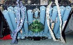
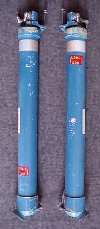 Another design that was tested on a Martin-Baker Aircraft Mk. GRU-5 seat
was the Rocket Power Incorporated (RPI) seat back rocket system. This consisted
of two tubular rockets flanking the main beam assembly. Both rockets had nozzles
that were canted down and outward from the seat centerline to provide a more
stable launch. A similar design was adopted in the Stencel S-III-S seat system. The rockets pictured to the left are training rockets from the SEU-3A version of the S-III-S seat. This is the version used in the AV-8A Harrier. As mentioned above, the catapult system in the S-III-S is a dual catapult system with the two catapults on either side of the seat back, just inside the seat back rockets.
Another design that was tested on a Martin-Baker Aircraft Mk. GRU-5 seat
was the Rocket Power Incorporated (RPI) seat back rocket system. This consisted
of two tubular rockets flanking the main beam assembly. Both rockets had nozzles
that were canted down and outward from the seat centerline to provide a more
stable launch. A similar design was adopted in the Stencel S-III-S seat system. The rockets pictured to the left are training rockets from the SEU-3A version of the S-III-S seat. This is the version used in the AV-8A Harrier. As mentioned above, the catapult system in the S-III-S is a dual catapult system with the two catapults on either side of the seat back, just inside the seat back rockets.
In the days of the Century-Series fighters (F-100 thru F-105), the seats were
equipped with relatively simple ROCATs and the variance between the CG and
center of thrust tended to promote higher seat/man separation speeds.
This feature was not particularly
good for a couple of reasons, one of which was the additional tumbling added
time and distance prior to the parachute deploying. This was particularly a
problem at low altitudes, such as during takeoff and landing. One particular
seat that received a bad reputation for this was the Lockheed C-2 seat used in
the F-104. The statistics do not confirm this, and indeed show that the C-2 had
similar success percentages as the other seats of the era. The C-2 seats
envelope was not intended to fully encompass ground level ejections (until
the Weber gun-deployed parachute was added) and as such,
the seat was operating as designed. In Europe, the C-2 was seen as a dangerous seat
and was replaced in many countries F-104s with a Martin-Baker seat, which, was
fully qualified as a low level seat.
To counter the stability problem with these seats, several methods were tried,
starting with the drogue parachute. The Germans used a drogue chute on an early
nose capsule to slow and control it after it separated from the aircraft. This
allowed the pilot time to bail out of the capsule.
Martin-Baker Aircraft utilized a drogue chute from their earliest designs to
keep the seat from tumbling and slow it down. This chute was deployed by a
drogue gun unit (DGU) mounted on the side of the seat beams. In early seats this
drogue was fairly large and allowed the crewman time to manually separate from
the seat. MBA discovered in early trials that the chute could be held in the
aerodynamic wake of the seat and would not deploy in a timely fashion, so the
DGU was designed and aimed to fire it into clear air. At high speeds the large
drogue would tend to be damaged by the opening forces so as the chute was made
smaller, another drogue was added as well. This smaller drogue was deployed
first and slowed the seat fractionally while pulling out the larger drogue. Once
the seat was slowed down enough, which in later models was sensed by a ‘G’
switch, the Timer Release Mechanism would release the drogue chutes and allow
them to extract the main parachute.
Several other seat companies use drogue chutes to slow and stabilize the seat,
including Douglas Aircraft Company's in the ACES II seat. As will be seen later, the
ACES II mainly uses the drogue system to slow the seat and provide yaw and pitch
stabilization in the higher speed modes. (In Mode 1, the very low speed range, the
drogues are not deployed.) The ACES II drogue is a duplex system as well.
This drogue system, like
the later versions of the Martin-Baker Aircraft drogues, and the Stencel Aero
Engineering S-III-S drogue (among others) use multiple attachment points to keep
the seat/man package facing into the relative wind. In the Martin-Baker Aircraft
and Stencel Aero Engineering systems, the lower drogue bridles are disconnected
after the seat has slowed, which allows the seat/man package to orient in a foot
first position prior to main parachute deployment. The Douglas Aircraft Company
ACES II severs the two drogue bridles completely separating the drogue from the
seat prior to main deployment.
The Stencel Aero Engineering Directional Automatic Realignment of Trajectory
(DART) system consisted of an under seat mounted package which included a ‘slack
line’, a ‘slip line’, a brake assembly and a bridle. The basic operation of the
system was that the slack line would pay out as the seat ejected for a specified
distance, then the brake assembly (which could be aircraft mounted) would play
out the slip line in a controlled fashion. The bridle assembly helped align the
forces on the bottom of the seat pan to keep the seat pitch and roll actions to
a minimum. The DART system was retrofitted to a number of seats including the
late model F-100 seats, and many variants of the Douglas Aircraft Company's Escapac
series.
Another concept was the stabilizing boom elements that were fitted to several
seats. The booms were similar in design to the telescoping antennas common to
many appliances. The stabilizing booms were cartridge actuated to extend and
mounted in various locations on the seats or capsules which used them. The F-106
‘Rotational B’ seat used a pair of them which extended upwards from the back of
the seat once it was rotated over onto its back, where the XB-70 and X-15 seats
used booms mounted at the lower rear. No matter the location, the booms all were
intended to keep the seat/man mass oriented to the relative wind, and thus
stable. Similar stabilizing booms are used today in the Zvezda K-36 family of
seats.
Later still, the Douglas Aircraft Company Stabilization Package (STAPAC) was
developed. The STAPAC uses a gyroscopic mass and a set of pulleys to rotate a
smaller rocket. This rocket provides thruse in the opposite direction of the pitch
rotation to halt the adverse pitch as quickly as possible. Some early STAPACs used
a notched bar known as a rack which was attached to the cockpit floor and would
spin up the gyro wheel as the seat moved, but most are equipped with a gas generator which pulls in a rack to spin up the gear-like gyro mass to approximately 17,000rpm. The STAPAC
is primarily effective in the lower speed ranges, below 300kts. At higher speeds, the drogue
parachutes provide the required stability.
Recent developments have been done with computer controlled rocket nozzles.
These allow for much more capability than previous generations of seat
technology. This is because they are linked with an inertial guidance package on
the seat and can vector the thrust to reduce pitch, roll, and/or yaw. In cases
where the seat is fired near, or on, the ground, the rockets can be controlled
in such a manner as to cause the seat to gain altitude prior to seat separation
and parachute deployment. Versions of this technology have been tested with a
highly modified ACES II seat called the Fourth Generation Seat. The Fourth
Generation Seat used a very large ‘H’ shaped rocket in its back that used four
pintle nozzles from Aerojet Propulsion to control the thrust vectors. This seat
showed much promise in its small number of tests.
Two versions of underseat rockets have been developed as well, the MAXPAC, which
was tested on a stationary ACES II, and a Martin-Baker Aircraft underseat rocket
with pintle nozzles. These items have not been accepted for use yet although
Martin-Baker Aircraft is testing the underseat pintle rockets for future use.
Another type of stabilizing concept is a set of airbrake-like devices that
Martin-Baker Aircraft has fit to several versions of the Mk. 16 seat, including
the Mk. 16F for the Rafale, and the Mk. 16A for the Eurofighter. This consists
of a pair of flaps along the seat pan which are hinged at the front to expand
into the airflow and a plate on the headrest to slow the seat as well as give it
some stability. The NACES 2000 design was tested with a pair of flat stabilizers
which would extend sideways from the side of the main beam assembly and provide
a rudder-like control.
Note 1: In this paper to simplify the history seats and systems are attributed
to the company which first manufactured them.

 Martin-Baker Aircraft developed a multi-stage, telescoping catapult that uses a
primary cartridge at the top to begin seat movement. As the gas from this
cartridge expands inside the inner tube it forces the inner tube upwards,
driving the seat/man upward with a relatively low onset rate. As momentum builds
while the seat rises, ports in the outer tube of the catapult gun are uncovered
as the inner tube slid by. This allows the hot gas to enter the secondary charge
and ignite it. The additional gas pressure generated accelerates the extension
of the tubes and thus increases the speed of the seat/man mass. Since this
acceleration has been delayed, the onset rate is kept in reasonable bounds.
The photo to the right shows a secondary charge cartridge to the left of a primary catapult cartridge.
Martin-Baker Aircraft developed a multi-stage, telescoping catapult that uses a
primary cartridge at the top to begin seat movement. As the gas from this
cartridge expands inside the inner tube it forces the inner tube upwards,
driving the seat/man upward with a relatively low onset rate. As momentum builds
while the seat rises, ports in the outer tube of the catapult gun are uncovered
as the inner tube slid by. This allows the hot gas to enter the secondary charge
and ignite it. The additional gas pressure generated accelerates the extension
of the tubes and thus increases the speed of the seat/man mass. Since this
acceleration has been delayed, the onset rate is kept in reasonable bounds.
The photo to the right shows a secondary charge cartridge to the left of a primary catapult cartridge.