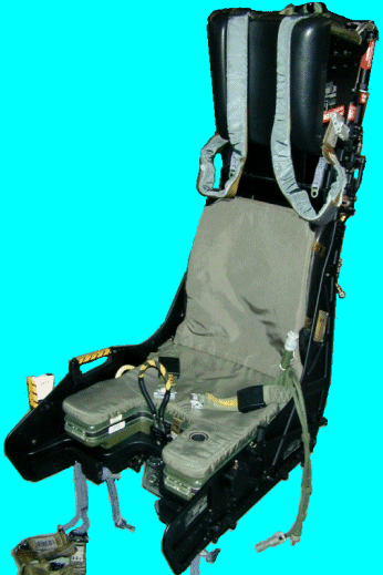
 This seat is one of the latest acquisitions of Chris Woodul. It is a SJU-5 seat from a F/A-18 Hornet. The photos show it after Chris has disassembled, cleaned and painted the seat (including the yellow and black striped handles on the sides of the seat bucket. He does those with several coats of paint!). Except for the currently incorrect risers, the seat is nearly complete. The underseat rocket is missing as are all the pyrotechnics. The SJU-5 (and SJU-6) seats are Martin-Baker Mk. 10 variants like the Mk. 10A for the Tornado, and the Mk. B10N used in the Alpha Jet.
I have included a pair of photos Chris took right after he recieved the seat showing the partially disassembled seat. This allows for viewing of the main beam assembly showing the wide inertia reel unit spanning the beams above the bucket raising/lowering motor. The drogue gun unit is clearly visible with the barrel removed near the top of the left beam. Also well shown is the seat bucket mounts which are a pair of tubes mounted in front of the main beams with a set of four bolts that extend forward into the seat bucket to allow the bucket to be easily removed in the cockpit for maintainance. These bolts are attached to two cross mounted units which are raised and lowered by an electrical motor.
In the picture of the front of the seat the ejection handle is visible above the clear plastic casing which normally holds the two machanically-fired gas initiators which start the ejection process. The gas from these cartridges is vented through hoses under the bucket into a set of sliding tubes called trombones on the sides of the beam assembly and up to the sear removal initiator on the top of the main beam. This is visible in the pictures of the partially disassembled seat. Note the yellow flaps on the back of the seat bucket covering the tops of the trombone connections in this picture. The catapult cartridge initiator has been removed and the opening into the catapult chamber is visible under the sear removal assembly with its redundant gas lines on the top of the beams.
| 3/4 Left view |
| Looking down the top left |
| Front view |
| Looking down the top left of the main beam assy with the seat bucket and cleaning products in front. This is before restoration. |
| Looking down the front of the main beam assembly. This is before restoration. |
Thanks to Chris for allowing me to use these photos.
| The Ejection Site Home | |
|---|---|
| Send email to Kevin |