Some views of ACES II seats are available here:
|
|
Pictures and diagrams will be added as they become available.
Some views of ACES II seats are available here: |
|
The Advanced Concept Ejection Seat (ACES) was designed to be rugged and
lightweight compared to earlier systems. It also was designed to be easy to maintain
and updatable. It includes the following features:
The ACES II is a third-generation seat, capable of ejecting a pilot from
zero-zero conditions up to maximum altitude
and airspeeds in the 600 KEAS range. The peak catapult accelleration is
about 12gz. The ACES II
has three main operating modes, one each for the low speed/low altitude,
medium speed, and high speed/high altitude. In Mode 1,
which includes 0-0 up to 250kts,
the parachute is inflating in less than two seconds. In
Mode 2 the chute is
inflating in less than 6 seconds. Mode 2 is effective up to the maximum
rated speed of the seat. Mode 3
deployment is delayed by the sequencer until the seat-man package
reaches either Mode 2, or Mode 1 conditions,
whichever comes first. Primarily, Mode 3 refers to operation above
15000 feet where separation from the seat would result in disconnection
from the emergency oxygen, and also possible lead to more severe opening shock
of the parachute due to differing atmospheric conditions.
Seat modes are selected by the sequencer based on atmospheric conditions, and the modes vary depending on differences in the conditions such as apparent airspeed and apparent altitude.
A light-weight crewman would reach an apogee of close to 200 feet if they ejected at ground level with zero airspeed. Typical performance is as follows:
| Aircraft Attitude | Velocity Knots |
Altitude Required |
| 0-Deg Pitch, 60-Deg Roll* | 120 | 0 |
| 0-Deg Pitch, 180-Deg Roll | 150 | 150 |
| 0-Deg Pitch, 0-Deg Roll | 150 | 116 |
| 10,000-FPM Sink Rate | ||
|---|---|---|
| -60-Deg Pitch, 0-Deg Roll | 200 | 335 |
| -30-Deg Pitch, 0-Deg Roll | 450 | 497 |
| -60-Deg Pitch, 60-Deg Roll | 200 | 361 |
| -45-Deg Pitch, 180-Deg Roll | 250 | 467 |
| * For this case, impact occurs at the instant the seat and aircraft are separated. In all other cases, conditions are at initiation of the catapult rocket. |
||
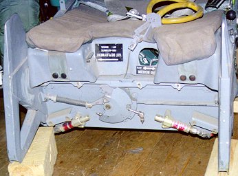
The seat structure is primarily aluminum alloy stamp formed with ridges for structural strength. The box-like structure is refered to as a monocoque construction. The back section which is nominally 16 inches wide has a set of three rollers on each side which interface with the extruded aluminum rails in the cockpit. These rails are identical to the rails used for Escapac seats (also a Douglas Aircraft {McDonnell-Douglas} product). The seat bucket is wider with a maximum width of 20 inches. The seat itself weighs approximately 127 pounds in most versions, with the rocket-catapult weighing 21LBs. The propulsion is a CKU-5/A/A rocket-catapult which uses a conventional solid propellant catapult charge to start seat movement, and a solid-propellant rocket motor to sustain the movement. The rocket motor is ignited at the end of the catapult stroke as the seat leaves the aircraft. The rocket-catapult is attatched to the seat at the headrest end and to the cockpit at the base via a twin-barrel linear actuator which provides for seat height adjustment. The nominal adjustment range is +2.5-inch vertical adjustment. The actuator is attatched at the fixed base to the cockpit structure and at the upper end via twin screw barrels to the base of the rocket-catapult. I have recently recieved information that the CKU-5/A/A is being phased out and replaced with the more environmentally friendly propellent version known as the CKU-5/B.
Seat functions are normally activated by the Recovery Sequencing Subsytem which consists of the environmental sensing unit , and the recovery sequencing unit, an electronic box located inside the seat rear on the right hand side. The environmental sensing unit consists of two altitude compensated dynamic pressure transducers, and two static pressure transducers. The dynamic pressure sensors (pitot tubes) are located on or near the headrest and read the air pressure as the seat exits the aircraft. The pressure differential between them and the ambient (static) sensors behind the seat is compared by the recovery sequencing unit to determine what operating mode the sequencer should select. The sequencer is fully redundant with two thermal batteries, two electrical systems, and an individual bridge wire from each in each of the electro-explosive squibs. The thermal batteries are activated by hot gas bled off from the catapult firing. There is a small window on the right side of the seat back to check the batteries for signs that they have been fired.
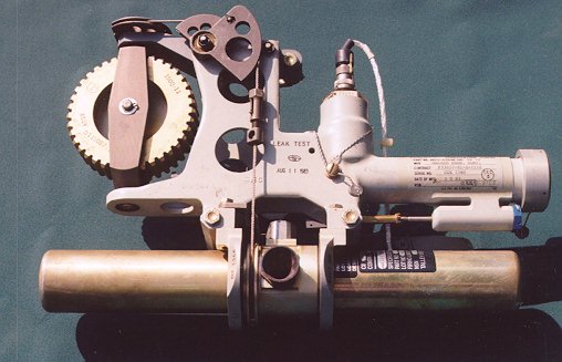
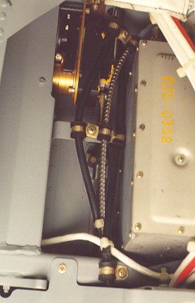
Firing of the seat is normally by pulling one of the ejection control handles mounted on the seat bucket sides. (On ACES seats fitted to F-16s and F-22s the ejection control handle is located in the center of the front of the seat bucket) The side pull handles are mechanically linked so that raising one will lift the other as well. Raising the handles actuates a pair of initiators via mechanical linkages. See below for the basic sequence of events that follows. On the F-16 the center pull handle rotates a bellcrank to pull the pair of linkages visible in this picture to withdraw the sears from both initiators. This seat was fired, and the sears are seen dangling from the linkages. In the left of the picture is the spring which provides the resistance to the pull making it about a 40-50 lb pull. On the right side of the picture is the linkage from the safety handle which locks the bellcrank mechanism.
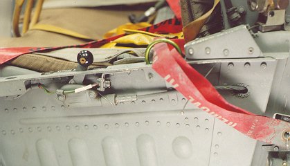
One particularly unique feature to the ACES II (and a few ESCAPAC seats) is the STAPAC package. STAPAC is a vernier rocket motor mounted under the seat near the rear. It is mounted on a tilt system controlled by a basic pitch-rate gyro system. This system is designed to help solve one of the great problems inherent to ejection seat systems. Center of mass/Center of gravity is extremely important in terms of keeping the thrust of the booster rocket from inducing a tumble. Rocket nozzles for the main boost of a seat are aligned to provide thrust through the nominal center of gravity of the seat-man package. The STAPAC provides a counter force to prevent extreme pitching in cases where the CG is off by up to +2 inches. This picture displays a F-16 ACES II from below. The STAPAC is visible as is the seat separation rocket on the left side. The seat is resting on its front and a pair of ground handling skids are mounted on the seat sides. The yellow flag is a safety pin preventing accidental firing of the STAPAC. The white colored lines are from the sequencer, and the twin firing initator cartridges are visible at the lower front with the black pyrotechnic lines leading from them.
Another unusual feature is related to the survival kit. In most ejection seats the survival kit is a rigid fiberglass box that makes up the seat inside the seat bucket. The ACES II survival kit is a soft pack that is stored under a fiberglass seat lid that is hinged at the front. When the pilot separates from the seat, the straps that connect him to the survival kit lift the seat lid up and forward. The seat kit then slips free from the rear end. The seat lid is latched in place normally, and released at seat separation when the Restraint Release Cartridge fires and rotates a bellcrank that releases the seat lid, shoulder harnesses, lap belt, and chute mortar disconnect. On the front of the seat bucket is a port that allows the crewmember to select the operation mode of the URT-33C survival beacon. The port also has a switch that allows the crewman to select automatic deployment of the seat kit, or manual deployment. For the URT-33C beacon, in the AUTO mode, the beacon would activate at man-seat separation. (For maintainance, a equipment release knob is located at the top rear of the right side of the seat bucket.)
The Inertia Reel Harness Assembly is located in the center of the seat back just below the headrest. The inertia reel fulfills two functions: (1) it acts like the shoulder belt in a car, restraining the pilot against a 2gx forward (-x) motion. (2) upon ejection, it retracts the pilot to an upright posture to minimize the possibility of spinal damage due to spinal misallignment upon catapult ignition. On the left side of the seat bucket there is a handle which allows the crew member to manually lock the reel prior to intense manuvers or landing to prevent possible injuries.
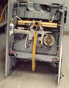
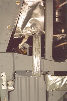
The Drogue System consists of a hemisflo chute, a small extraction chute, and the Drogue Mortar. The drogue mortar is fired in Mode 2 and Mode 3 to slow and stabilize the seat-man package. This is intended to prevent or limit the injuries to the crewmember as he/she is exposed to the windblast after exiting the aircraft. The mortar fires a 1.2 Lb slug of metal that draws the extraction chute out which by means of a lanyard deploys the drogue chute. The extraction chute is packed in a small wedge-shaped container on the upper left rear of the seat covered with metalized fabric. The lanyard is also covered in the metalized fabric. The drogue mortar is below this, and the drogue is packed in the metal covered box below this. The lid to the drogue is retained by a small plunger unit that is held in place by machining on the slug and released when the mortar fires. The drogue bridles are attached on either side of the seat. Many of these features are visible in this pictureThe bridles are wrapped around a set of rods and are cut by a set of pyrotechnic cutters when the sequencer determines that it is time to jettison the drogues prior to main chute deployment.
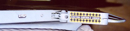
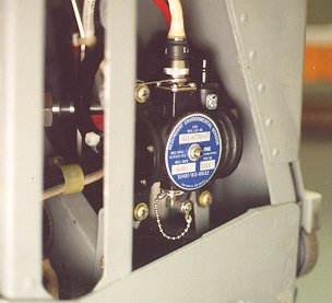
The seat is safed by means of a Safety Lever on the left side of the seat bucket which prevents the seat from being fired when the lever is in the up/forward position. When it is down/back flat against the side of the bucket, it allows the seat to be fired. The picture shows a F-16 handle in the Safe position. This picture shows a fired seat with the handle in the armed position. Note the firing handle is pulled out and resting on the seat cushion. The small tab on the handle engages a microswitch in the hole in the seat bucket side to electrically report to the aircraft the arming state of the seat.
The Emergency Manual Chute Handle is located on the right hand side of the seat bucket, and functions to fire the main chute mortar and initiate seat separation in case of failure of the electronic sequencer. Unlike other seats, the manual chute handle is inhibited in the aircraft and prevents the systems from functioning while the seat is still in the rails. In the event of ground egress, the crewman would have to unstrap the two shoulder harness connections, the two seat kit connections and the lap belt prior to egressing the aircraft. Given the 0-0 capability of the seat, in any case requiring extremely rapid egress, ejection would be a viable alternative. In early seats this function did not include the mortar cartridge and the handle was labled 'Restraint Emergency Release'. Pulling it would unlatch the same items, but relied on the pilot chute in the headrest to deploy the main parachute. The recommended procedure was to pull the handle with the right hand and push up on the pitot tube extensions with the left for more positive extension. On seats like the B-1B which had folding pitot tubes this was not an option, and the additional mortar cartridge was added. This picture shows both handles, the early one from a fired seat, the second from a live seat, showing the safety pin installation as well.
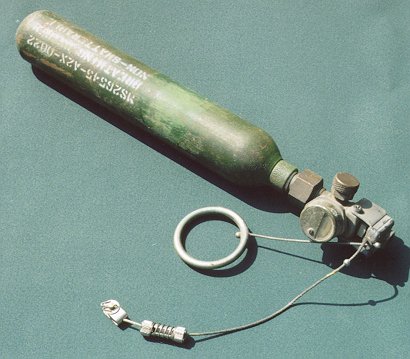
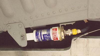
The emergency oxygen system consists of an oxygen bottle attached to the seat back, an automatic activation lanyard, and a manual pull ring (the green ring visible on the left hand seat pan side in this picture). As the seat rises up the rails, the lanyard activates the oxygen bottle and allows the crewman access to oxygen as long as he is still connected to the seat. During an in-flight emergency that does not require ejection, the oxygen bottle provides breathable air for enough time to return the aircraft to 10000 feet or below where the atmosphere is thick enough for the pilot to breath.
| ACES II Event/Time Sequence | |||||||
|---|---|---|---|---|---|---|---|
| Typical Event | Mode 1 | Mode 2 | Mode 3 | ||||
| Rocket-Catapult Fires | 0.0 | 0.0 | 0.0 | ||||
| Drogue Deploys | Note 2 | 0.17 | 0.17 | ||||
| STAPAC Ignites | 0.18 | 0.18 | 0.18 | ||||
| Parachute Deploys | 0.20 | 1.17 | Note 1 | ||||
| Drogue Releases from seat | Note 2 | 1.32 | Note 1 | ||||
| Seat Releases from Crewman | 0.45 | 1.42 | Note 1 | ||||
| Parachute Inflates | 1.8 | 2.8 | Note 1 | ||||
| Survival Kit Deploys | 5.5 | 6.3 | Note 1 | ||||
| Note 1: In Mode 3 the sequence delays until the conditions drop below the Mode 3 boundry, then the parachute deploys after a 1.0 second delay. | |||||||
| Note 2: Drogue Chute is not deployed in Mode 1 Ejections, but the drogue line cutters will fire to make sure. | |||||||
| Note 3: The info in this table is for the F-15/F-16/F-117. Other seats have slightly different timings. | |||||||
| ACES II Explosives
Mechanical and Electro-explosive |
|---|
| (2) JAU-8/A25 Ejection Initiatiors for the left and right ejection control handles. |
| (1) Inertia Reel Gas Initiator which provides ballistic pressure to propel grease into the inertia reel that locks the pilot back into the seat upon ejection. |
| (1) Pitch Stabilization and Control Assy (STAPAC) which includes a gas grain generator and a vernier rocket which is ignited by the #2 P-lead from the Recovery Sequencer. This STAPAC is used to stabilize and correct for the pitch axis of the seat during a MODE 1 (low and slow) ejection. The STAPAC fires in all modes of ejection. |
| (1) Drogue Gun Cartridge for the drogue gun. This cartridge fires the drogue gun which propels a 1.2 pound slug into the airstream and to deploy the extraction chute, and eventually the hemisflow drogue chute, to slow down and stabilize the ejection seat during a MODE 2 or 3 high speed ejection. This drogue gun is fired from electrical voltage provided to P-3 from the Recovery Sequencer. |
| (2) Mortar Disconnect Assy. Cartridges fired by the #4 P-lead (primary cartridge) and P-11 from the emergency power supply (secondary cartridge) that is used to propel and deploy the recovery parachute. |
| (2) Severance Cutters that is used to cut away the drogue chute in all three modes of recovery. (The drogue chute is not deployed in MODE 1 but the bridle lines are cut anyway by the sequencer. This simplifies the sequencer by not adding the additional function needed to prevent the cutters from firing.) The cutters are fired from the # 5 and 6 P-leads from the Recovery Sequencer. |
| (1) Restraint Release Cartridge that is connected to the P-7 lead from the Recovery Sequencer. This component, when fired, rotates the bellcrank down and releases the lap belts, inertia reel straps, seat pan latch, and primary mortar disconnect pin. |
| (1) Emergency Mortar Cartridge that is connected to the P-11 lead from the Recovery Sequencer. This is used to fire the main chute mortar either in the event of a failure (or suspected failure) of the sequencer separation, or in the event that the crewman determines that it is in his/her best interest to separate from the seat earlier than the sequencer would. |
| (2) Reefing Line Cutters attached to the recovery parachute that fires 1.15 seconds after the recovery parachute is deployed. This delays the full inflation of the chute so the pilot does not get ripped in two by a rapid deceleration after it is deployed. Pilots just hate when they get ripped in two. |
| The Trajectory Divergence Rocket separates the two seats from each other in two place aircraft such as the F-15E and F-16D after ejection. It also functions to add a roll impulse to the seat in Mode 1 ejections that provides for greater separation between the crewman and the seat. The Divergence rocket is fired by P-9 of the recovery sequencer. Single seat F-16s are also fitted with a TDR as shown in this picture. |
A special thanks goes to MSgt Al Chase and his crew from the 177th FW NJANG egress shop for allowing me to visit and photograph one of the F-16 ACES II seats. He also arraigned for me to be able to examine and photograph another F-16 ACES II from the 58th FW VTANG which had recently been recovered five years after it was used to save the life of a pilot. The photos on this page are from those seats, and the F-16 ACES II that has recently been added to my collection.
| The Ejection Site Home | |
|---|---|
| Send email to Kevin |