 The following are a few pictures of the SR-1 Ejection seat.
This is a Lockheed Design which is not much different from the Stanley designed Lockheed C-2 (later modifed into the
S/R-2) seat which preceded it in other aircraft [Note: the C-2 seat was
used in the very early A-12 and SR-71 Blackbirds as can be seen in the cockpit of A-12 06925]. Some of the differences between the C-2 and
the SR-1 seat include the omission of the leg guards and arm restraint nets which were
used on the C-2. Due to a fatality which occurred early in the SR-71 program where a
crewman was killed when his helmet impacted the headrest of the seat during a structural
breakup, some of the C-2 seats were equipped with a headrest extender to more closely fit
the seat to the crewman. The seat shown here (with incorrect padding on it)
shows a Blackbird C-2 with the headrest extension installed. Note the missing arm net stowage
'wings' standard to all other C-2 seats.
A later accident which involved failures on the C-2 seat
led to the removal of the headrest extenders, and the later redesign of the seat so that the
headrest were more forward without the extenders. This is apparently what led to the whole
redesign which created the distinct SR-1 shape of the seat bucket and headrest.
The following are a few pictures of the SR-1 Ejection seat.
This is a Lockheed Design which is not much different from the Stanley designed Lockheed C-2 (later modifed into the
S/R-2) seat which preceded it in other aircraft [Note: the C-2 seat was
used in the very early A-12 and SR-71 Blackbirds as can be seen in the cockpit of A-12 06925]. Some of the differences between the C-2 and
the SR-1 seat include the omission of the leg guards and arm restraint nets which were
used on the C-2. Due to a fatality which occurred early in the SR-71 program where a
crewman was killed when his helmet impacted the headrest of the seat during a structural
breakup, some of the C-2 seats were equipped with a headrest extender to more closely fit
the seat to the crewman. The seat shown here (with incorrect padding on it)
shows a Blackbird C-2 with the headrest extension installed. Note the missing arm net stowage
'wings' standard to all other C-2 seats.
A later accident which involved failures on the C-2 seat
led to the removal of the headrest extenders, and the later redesign of the seat so that the
headrest were more forward without the extenders. This is apparently what led to the whole
redesign which created the distinct SR-1 shape of the seat bucket and headrest.
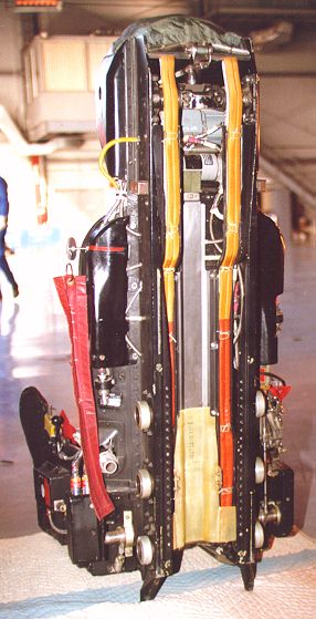
 The SR-1 includes connection points for the S-1030B pressure suit vent line. The parachute is
attached to the seat by a pair of inertia reel lines over the shoulders, and is connected to the crewman by Koch fittings. The parachute is also connected by a lanyard which on separation actuates the integral drogue gun in the parachute pack. This fires a slug over the crewman's left shoulder to begin the parachute deployment about 0.2 seconds after separation. Leg restraints
of the spur type are standard. To use them, the crewman dons a set of spur units on each
foot, and when seated in the seat connects them to the seat by means of a ball nipple visible in the
foot areas of the seat under the seat pan ledge. These restraints are connected to a set of reels
at the rear of the seat (on either side) where light tension is maintained by a spring. On
ejection, these reels are gas spun to retract the lines, pulling the crewman's feet back against
the seat. The cables for these restraints is routed through a set of cutters which are gas actuated
at seat separation.
The SR-1 includes connection points for the S-1030B pressure suit vent line. The parachute is
attached to the seat by a pair of inertia reel lines over the shoulders, and is connected to the crewman by Koch fittings. The parachute is also connected by a lanyard which on separation actuates the integral drogue gun in the parachute pack. This fires a slug over the crewman's left shoulder to begin the parachute deployment about 0.2 seconds after separation. Leg restraints
of the spur type are standard. To use them, the crewman dons a set of spur units on each
foot, and when seated in the seat connects them to the seat by means of a ball nipple visible in the
foot areas of the seat under the seat pan ledge. These restraints are connected to a set of reels
at the rear of the seat (on either side) where light tension is maintained by a spring. On
ejection, these reels are gas spun to retract the lines, pulling the crewman's feet back against
the seat. The cables for these restraints is routed through a set of cutters which are gas actuated
at seat separation.
The D-ring at the front center of the seat is cable connected to an initiator under the seat pan. The cable is spring mounted to prevent injuries after ejection and prior to seat separation at which time the cable is severed. When pulled, the initator gas is routed to the inertia reels to retract the crewman back upright. It is also routed to the foot restraint reels and via a quick disconnect fitting to the canopy removal system. As the canopy is jettisoned, an initiator in the canopy system is actuated and gas from it is directed back into the seat via another quick disconnect to actuate the gas-operated sequencing system, and to fire the catapult after a 0.3 second delay to allow the canopy to clear the area.
The Drogue chute is mounted in the headrest with the drogue gun mounted in the center of the rails behind it. It is fired 0.2 seconds after the gas from the canopy system begins the sequencing, at about the same time as the seat clears the aircraft rails. At that time, the rocket section of the rocket/catapult (ROCAT) is being ignited by gas from the catapult portion. Other portions of the seat system actuated by the canopy initiator include the arming of the pyrotechnic aneroids which sense altitude by air pressure and continue the seat sequencing when the seat is below 15,000 feet. Also, gas arms the lower drogue attach point cutters which will sever the lower riser lines 10.0 seconds later. This will allow the seat to decellerate, then the cutters will allow the seat to swing down under the 6.2 foot drogue decending in a controlled fashion until the aneroids fire at 15,000 feet.
When the aneroid units continue the seat separation, the following events happen:
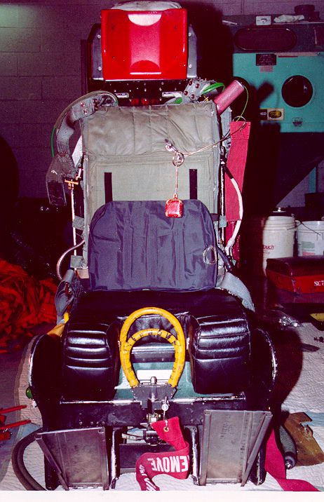
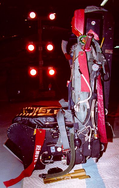
After separation, the survival kit is retained by straps connected to the crewman's harness on each hip. It is manually deployed by pulling the curved yellow handle inboard on the right side of the seat pan. The yellow and black striped handle barely visible under the oxygen connections in this picture is the manual scramble handle which mechanically and pyrotechnically executes most of the seat separation functions to allow the crewman to either egress the aircraft on the ground, manually bailout from the aircraft, or manually separate from the seat in case of a seat separation failure. The scramble handle disconnects the lanyard on the parachute so that it must be manually actuated by the D-ring on the left riser if the parachute is needed.
The yellow cover barely visible on the left of the seat bucket protects the secondary catapult T handle. This handle is used if there is a failure of the seat to fire normally. The canopy must be jettisoned prior to using this handle as the seat will fire immediately on pulling the T handle. To prevent the T handle from being used as the primary handle, the D-ring must be pulled first to arm the T handle.
The yellow pyrotechnic hose visible on the left side of the seat near the headrest is the Rocket Catapult connection. In case of a crash, the crash rescue crew would sever that line with bolt cutters to prevent accidental firing of the rocket while rescuing the crewman.
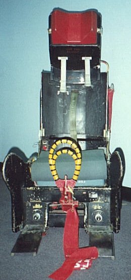
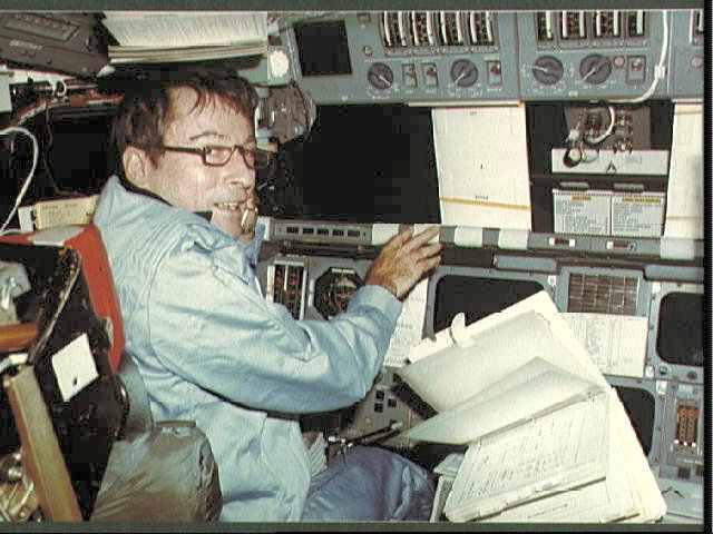
The SR-1 seat has a few known variants, the most common of which is the seat used in the later model U-2 aircraft including the U-2R, TR-1, and ER-1 That variant is know by the designation RQ201. The main modifications for the RQ201 are the secondary ejection handle has been relocated to the left side, and the double-d ring is replaced with a single loop d-ring. A SR-1 variant was also used in the Enterprise and Columbia Space shuttles. The Shuttle seats were fitted for the landing tests at Edwards AFB, and for the first four flights (STS-1, STS-2, STS-3, and STS-4) in orbit. The Shuttle version had a tilting back to position the pilots closer to the instrument panel while the shuttle was on the pad. This seat, with the necessary pressure suit (the shuttle astronauts, SR-71, and U-2 pilots all use David C. Clark suits) is the highest altitude/ highest airspeed rating in current United States service. Even though the seats are rated for high speed, they are not High Dynamic Pressure seats. High dynamic pressure (High-Q) is a function of air density as well as speed. The SR-71 flys at high altitudes where the air pressure is significantly lower, lowering the dynamic pressure. The SR-71 flying at 2000mph at near 80,000 feet is actually experiencing wind force more equivalent to about 460 MPH (400 Knots Equivalent Air Speed {KEAS}). Aircraft such as the FB-111 were designed for higher speeds down in the thicker atmosphere, and thus experience a much higher 'Q' or dynamic pressure.
| Blackbird Seat, Front |
| Blackbird Seat, Left side |
| Blackbird Seat, Right Side |
| Blackbird Seat, Rear |
| Blackbird Seat, Top with Drogue cover open |
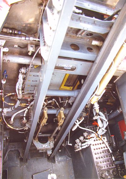
| Blackbird Cockpit sans seat |
| Blackbird Seat, Top with Drogue cover open |
| Diagram of Blackbird Seat Rear with labels |
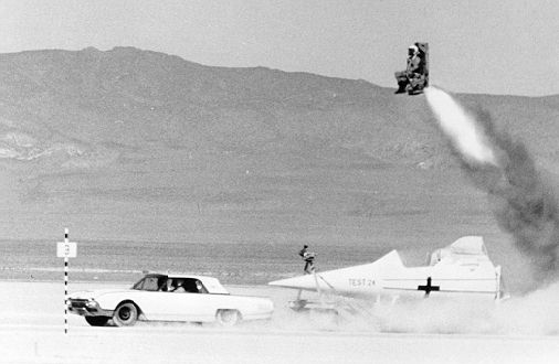
| Sled test of a C-2 Seat from an A-12 cockpit mockup being towed across the desert by a Ford Thunderbird |
| Space Shuttle seat |
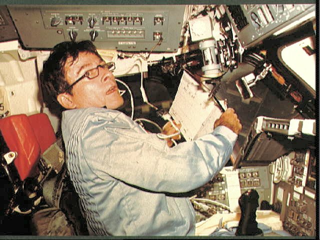
| Photo from the First flight of the Space Shuttle (Showing Astronaut John Young on the flight deck.) |
| Another Photo from the first flight of the Space Shuttle |
| Thanks to Tony Landis for use of most of these photographs, also to Richard Graham COL. USAF Ret. for use of the photo of the Space Shuttle seat, and to NASA for the archive photos of the second flight, and the survival kit photo. COL. Graham's photo was originaly published in his book 'SR-71 The Inside Story'. For more information on this excellent book, click here |
| The Ejection Site Home | |
|---|---|
| Send email to Kevin |