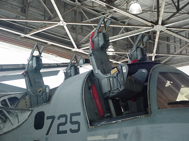
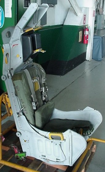
These undated photos show an S-3 Viking and its Escapac IE-1 seats being maintained. This seat is one of the Escapac variants fitted with the STAPAC rocket (see the ACES II Technical page for details) and is sometimes refered to as the Escapac II configuration. Since the main Escapac page details most of the seat system this page will only have a few detail photos for comparison.
As you can see in the top picture, during some of the maintainance procedures, the seats do not need to be fully removed from the aircraft. In the S-3 this is possible due to the configuration of the cockpit which allows the egress technicians to reach large areas of the seats after raising them. First, the crews must disconnect the electrical and pyrotechnic connections, removing the survival kit and parachute and unbolt the upper catapult connection. Then the seats may be raised and pinned in place near the top of the seat rails as can be seen in this photo. The lower two sets of rollers are still engaged in the rails which keeps the seats steady.
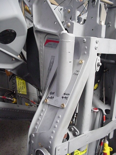
Under the seats the catapult can be seen between the rails. The lower end of the catapult is attached to the seat height adjusting motor which is the device with the squat black cylinder in between the two height adjusting rods. This one is near the top of the extension range as can be seen by the extended silver adjusting rods. On either side of the catapult against the bulkhead gas lines and initiators from the seat sequencing system are visible.
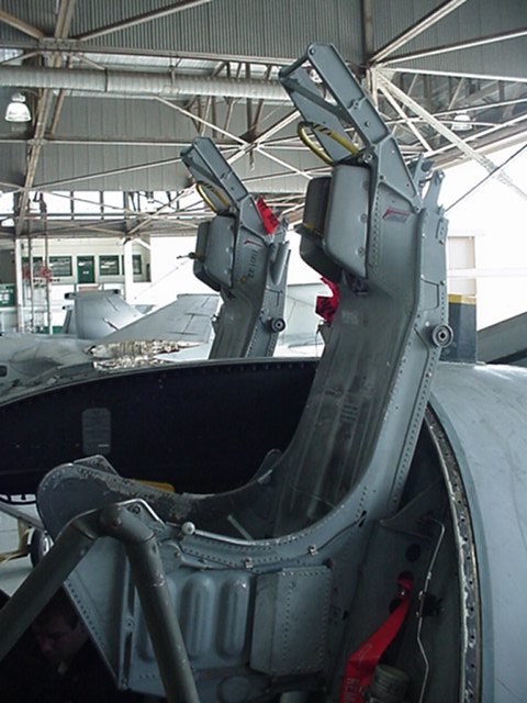
The STAPAC is protected by a coverplate visible in this photo. The photo also shows the linkages which release the pilot at seat separation. The thruster arm is visible at the right of the photo coming through the cross brace. This area of the seat is usually covered by a shield which has been removed in this picture. The large central hole in the bulkhead is for the catapult.
The seat separation is by means of a rocket over the left shoulder. This view shows the rocket installed in the seat. It is the cylinder vertically mounted alongside the headrest. Its nozzle can be seen pointing upwards and forwards. The plastic cover for the top of the headrest has been removed, revealing the catapult attachment bolt at the very top right of the photo.
Special thanks to the anonymous contributor who sent me these photos!
| The Ejection Site Home | |
|---|---|
| Send email to Kevin |