 The Ejection Site
Martin-Baker Mk. 9A
The Ejection Site
Martin-Baker Mk. 9A
The Ejection Site
Martin-Baker Mk. 9A
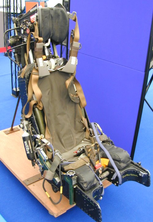 An interesting seat from Martin-Baker, this seat was fitted in the early Harrier jets. As the follow on to the Mk. 8A seat for the T.S.R. 2 aircraft, it included several features not previously seen in earlier Martin-Baker seats. The most obvious change from most Mk. 6/7 seats was to place the main recovery parachute in a flatter parachute box which doubled as the back rest. The parachute withdrawal line is routed via a slot in the center of the headrest cushion then through the guillitine mechanism which is visible in the front view just above the seat back.
The seat firing mechanism was modified with a system similar to the one used in the H7 series of seats. An initiator cartridge and firing mechanism on the front of the seat pan is fired by pulling the center handle on the seat pan. That withdraws the sear from the initiator and fires a cartridge. Gas from that cartridge is piped under the seat and up the rails to the seat mounted initiator behind the drogue gun. On receiving the gas pulse another cartridge is fired to rotate the ejection gun cross tube. This tube then withdraws the sear from the ejection gun. That in turn generates the impulse to begin moving the seat as this vintage of MB seats operates.
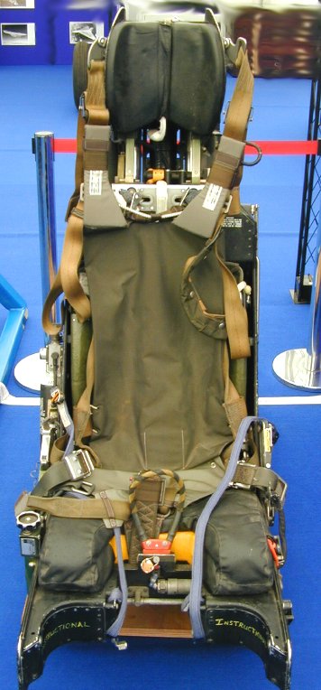
As the seat begins to move the ejection gun cross tube impinges on the MDC interlink rod, causing the MDC detonator unit to fire. The Mild Detonating Cord (MDC) system is used to fracture the plexiglass canopy to allow the pilot and seat to penetrate through it with minimal harm. As the catapult gun tube extends the seat moves up the slippers on the inside of the main beams, pulling two trip rods out. One starts the timer on the Drogue Gun Unit (DGU) and the other starts the Time Release Mechanism (TRM). These first fire the drogue gun to extract the drogue after the seat clears the cockpit, the later then initiates seat man separation after a delay. The catapult gun tube reaches a point about 1/4 of the distance it extends and allows the gas inside to vent into a secondary cartridge (pancake charge) which accelerates the seat movement further. While this is going on, under the seat a cable lanyard that is connected to the cockpit floor is unspooling from the bottom of the seat. Another distance travelled and the last pancake charge is fired allowing the seat to reach about 60 feet per second at seat catapult separation. The lanyard reaches maximum length at roughly this time and the underseat rocket sear is withdrawn allowing the rocket to fire and extend the acceleration away from the aircraft.The earlier versions of the seat were equipped with US-style torso harnesses, which were attached to the seat via a set of Koch fittings on the risers. This was changed in the early 1980s to the harness shown here. This harness uses four straps which connect to the center buckle just behind the seat firing handle. The shoulder straps are here held by clips tot he side of the headrest to allow for ease of the crew ingress and strapping in.
| Front view |
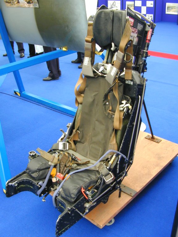
| 3/4 left view |
| 3/4 right view |
| Back view |
| Headrest area |
Thanks Chris for the use of the photos! Additional thanks go out to Steve Murray, former RAF armourer, for correcting some of my description!
| The Ejection Site Home | |
|---|---|
| Send email to Kevin |