 Crew Escape Technology (CREST) Ejection Seat
Crew Escape Technology (CREST) Ejection Seat
The Crew Escape Technology program was developed to explore technologies to allow for safer escape for seat occupants over a broad range of airspeeds and occupant conditions. The program was run by the United States Air Force with input from the United States Navy. The seat itself was developed under contract by Boeing Aircraft. Over the course of the 1980s and 1990s the CREST seat subsystems were developed. The subsystems investigated included windblast protection devices, adaptive restraint for better crew fitting, selectable thrust propulsion, digital flight control and a controllable catapult.
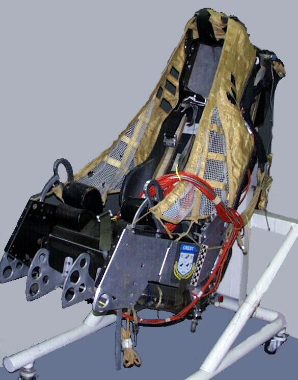
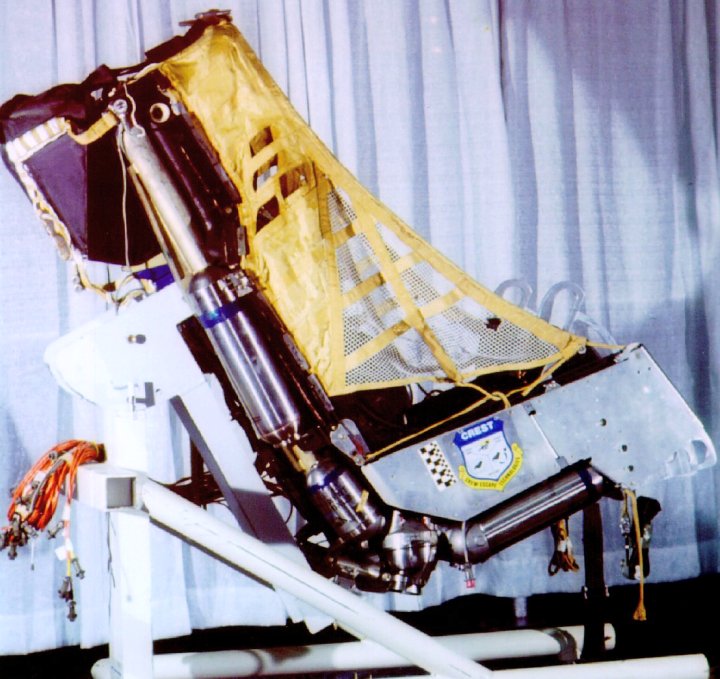
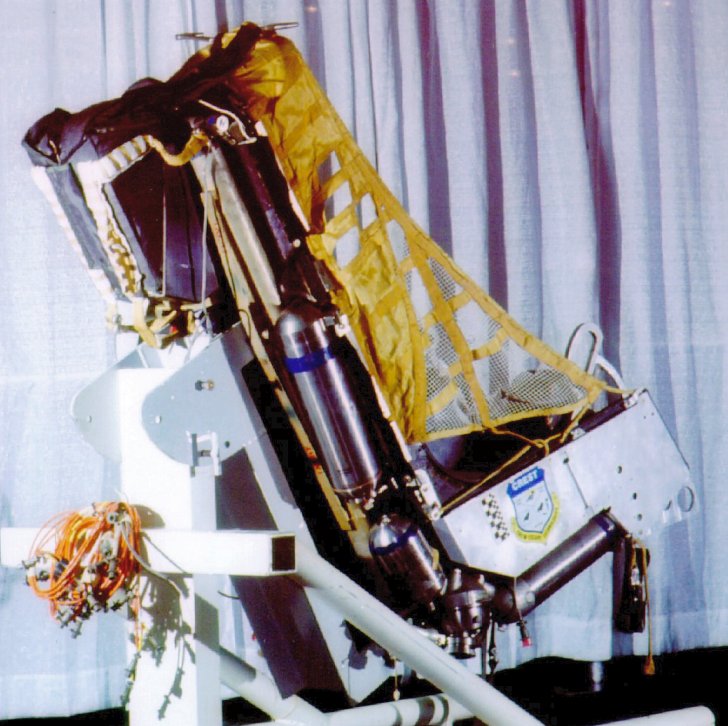
The propulsion system used constant thrust slewing nozzles for attitude control. The prototype seat, pictured to the left here incorporated an advanced multi-nozzle rocket system and was designed to provide a controlled stable ejection up to 700 KEAS from sea level to 70,000ft for the 95 percentile occupant. For the lighter weight 5 percentile occupant the seat was expected to be capable of providing protection from 650 KEAS at sea level and increasing to 700 KEAS at 70,000ft. The seat was calculated to be very good at adverse altitude, high sink rate ejections.
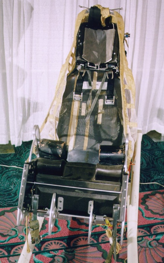
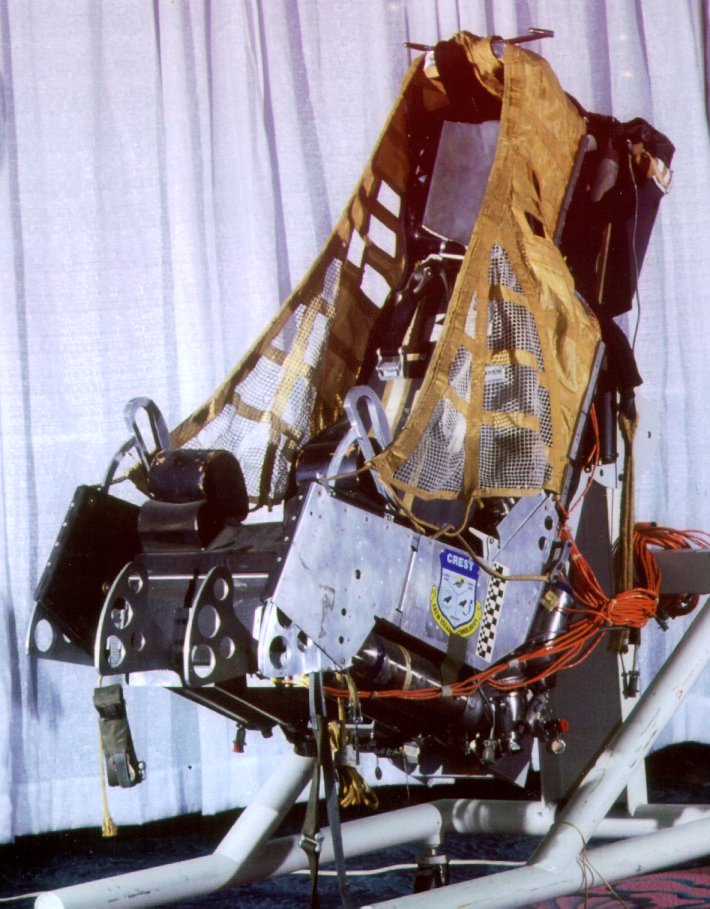
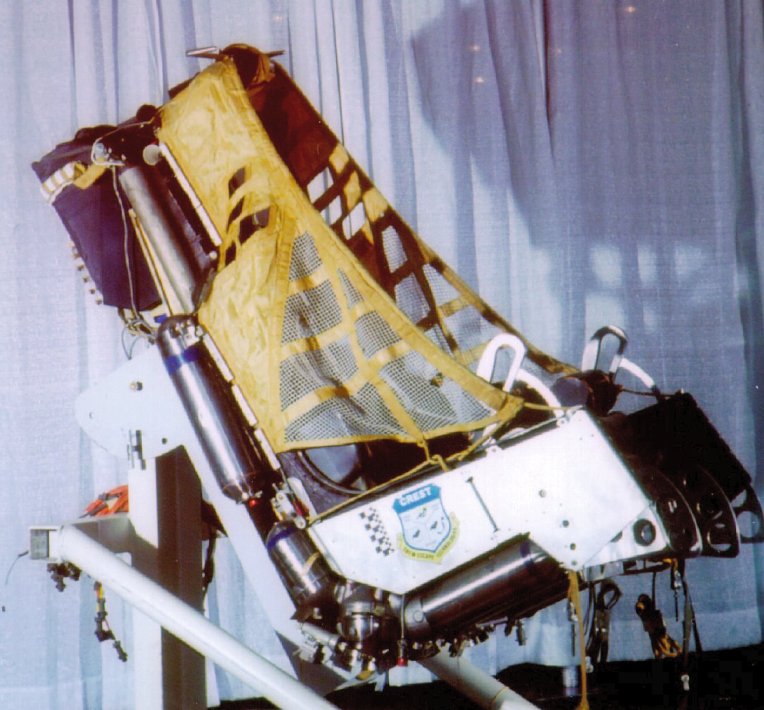
Among the features of the seat were the windblast protection provided by the retention netting shown deployed. This is coupled with foot anti-rotation fences, and a specialized haulback aircrew positioning system to place the aircrew in the best position for safe ejection. The windblast fence is shaped over the aircrew's head by an arch that also contains a pitot-static sensor system. Leg lifters and leg restraint lines were also planned for implementation.
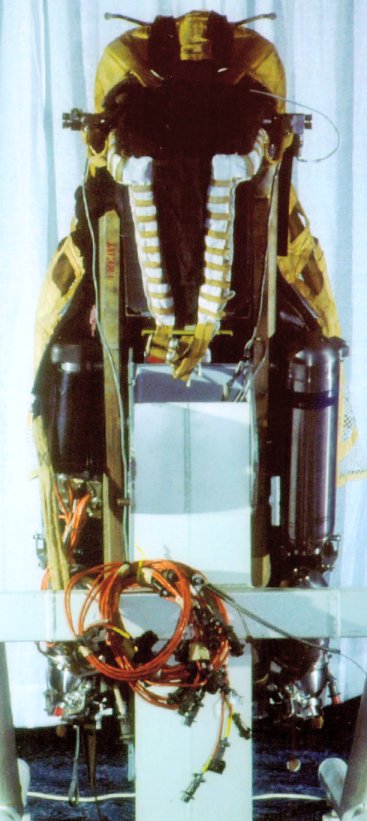
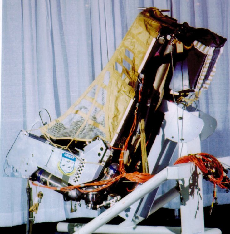
Also included beyond the aforementioned controllable nozzles in the propulsion system is a set of Attitude Control thrusters on either side of the headrest. The pair of thrusters are fed hot gas from a generator on the aft side of the seat, and operate as a single unit with a valve that vents gas to either side or both simultaneously. This valve and the pivoting nozzles are hydraulically powered by an Hydraulic Power Unit (HPU) internal to the seat. The HPU uses hot gas to generate the fluid pressure.
The Controller/Sequencer had the capability of controlling the catapult force based on several factors including a risk assessment made during the pre-ejection phase. This takes into account aircraft attitude and altitude as well as airspeed to make a determination of how much force is necessary to clear the tail of the aircraft. A thrust profile is selected for both the catapult and the rocket system. These profiles are then controlled as the seat is fired.
The aircrew packaging system was also controlled by the risk assesment and speed of the inertia reel haulback and hip haulback systems could be adjusted based on the risk assessment. The arm net fence included an system for deploying the fence outboard and then retracting it inboard to help capture the aircrew's arms if they were not in the optimum position for ejection.
Testing of individual componants up to a complete seat for windblast testing went relativly well. This testing including breadboarding of the controller/sequencer, software tests, hardware in the loop tests of the propulsion systems with the C/S and wind tunnel and windblast tests. The development program was complicated by several never before used technologies being tested. Most of these issues were resolved, however the military decided to terminate the program due to delays and budgetary issues.
The 4th Generation Ejection Seat prototype was developed as a low cost system for continued testing of some of the features developed in the CREST program.

Thanks to Alva Karl of Veridian, and to the Biodynamics and Acceleration Branch of the Air Force Research Laboratory for thier assistance in providing materials for this page.
This ejection seat was on display at theSAFE Association History of Escape Systems and the Evolution of Manikins Display during the SAFE Association 40th annual Symposium, October 2002