The Ejection Site
4th Generation Ejection Seat
4th Generation Ejection Seat
 The 4th Generation Ejection seat was developed as a technology demonstrator program to showcase some of the
technologies developed for the CREST Seat. By having a sled test demonstration of the propulsion, flight
control, and windblast concepts this seat would validate the capabilities for future projects. With AERO, Aerojet Propulsion Systems, McDonnell-Douglas
Aircraft (a subsidiary of Boeing Aircraft), and F&L Enterprises the USAF and USN developed and tested the seat. The key features of this seat included
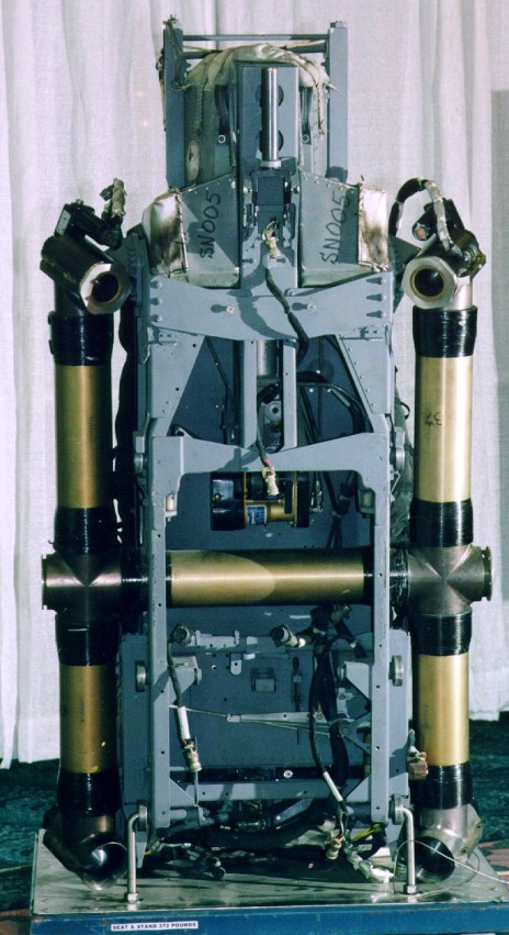
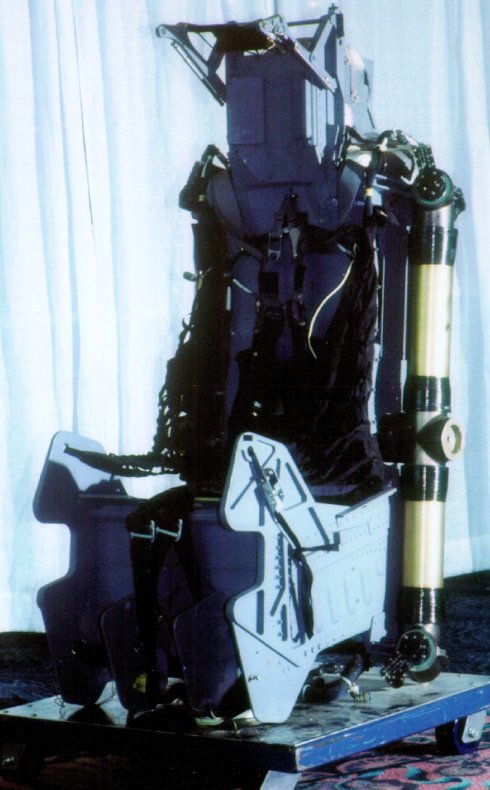
positive limb restraints, a brow device, and a pintle-controlled rocket engine. Using an F-16 ACES II as the base
chassis, the large 'H'-shaped rocket was installed in the back as can be seen in the picture to the left. This rocket consists of five tubes containing
propellant and four nozzles located at the ends of the tubes, two at the top and two at the bottom. Unlike previous ejection seat propulsion systems
these nozzles have the ability to control the thrust from each nozzle. This is accomplished by use of Aerojet-developed pintle nozzles which can vary
the amount of thrust from each nozzle. A control system working off feedback sensors on the rocket with inputs from an inertial navigation unit mounted
in the seat pan controlled opening and closing the nozzles. These nozzles were each tilted in a downward and inward direction, allowing the seat to be
controlled in pitch, roll, and yaw based on differential thrust. Doing this allowed the seat to control motion to counter wind forces and inertial movement.
Ground avoidance was also programmed and tested.
The 4th Generation Ejection seat was developed as a technology demonstrator program to showcase some of the
technologies developed for the CREST Seat. By having a sled test demonstration of the propulsion, flight
control, and windblast concepts this seat would validate the capabilities for future projects. With AERO, Aerojet Propulsion Systems, McDonnell-Douglas
Aircraft (a subsidiary of Boeing Aircraft), and F&L Enterprises the USAF and USN developed and tested the seat. The key features of this seat included
positive limb restraints, a brow device, and a pintle-controlled rocket engine. Using an F-16 ACES II as the base
chassis, the large 'H'-shaped rocket was installed in the back as can be seen in the picture to the left. This rocket consists of five tubes containing
propellant and four nozzles located at the ends of the tubes, two at the top and two at the bottom. Unlike previous ejection seat propulsion systems
these nozzles have the ability to control the thrust from each nozzle. This is accomplished by use of Aerojet-developed pintle nozzles which can vary
the amount of thrust from each nozzle. A control system working off feedback sensors on the rocket with inputs from an inertial navigation unit mounted
in the seat pan controlled opening and closing the nozzles. These nozzles were each tilted in a downward and inward direction, allowing the seat to be
controlled in pitch, roll, and yaw based on differential thrust. Doing this allowed the seat to control motion to counter wind forces and inertial movement.
Ground avoidance was also programmed and tested.
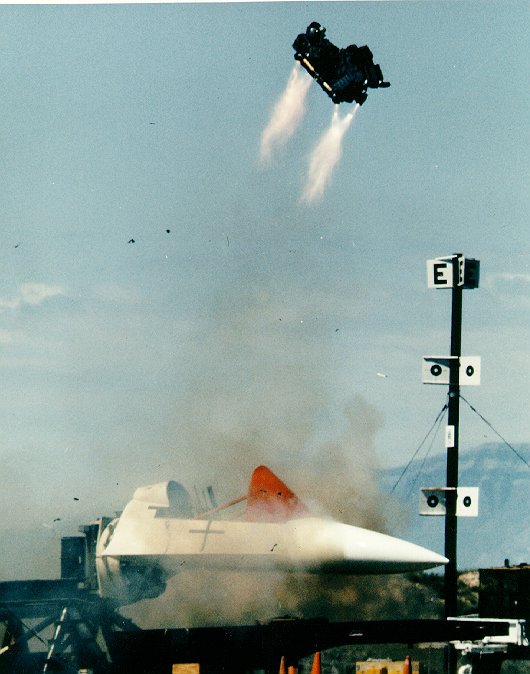
In a dramatic series of tests the 4th Generation seat was tested from zero-airspeed through 700 KEAS at the sled test facility at Holloman Air Force Base.
Although there were some problems with the tests, the technology performed very well. This photo shows an early zero
airspeed test. The seat has catapulted from the cockpit and the rocket has pitched the seat to a 45 degree angle for maximum effective trajectory. The seat
was shown to be capable of righting itself from a 60 degree roll at speeds from 0 to 320 KEAS and climbing for altitude before seat separation. At lower
speeds seat separation was also assisted by the pintle rocket system. Just prior to rocket burn-out the seat was commanded to pitch to have the lower end
facing into the relative wind. With the ACES II parachute mortar system designed to deploy the parachute upwards from the seat, this position allowed for
a very clean deployment and seat strip-off during separation.
At higher speeds, the seat would control attitude to prevent injury, and just prior to rocket burn-out would pitch into the best position for drogue
deployment. After deployment of the drogue, the seat would be slowed by the drogue until seat separation which would occur in the same manner as a normal ACES II seat.
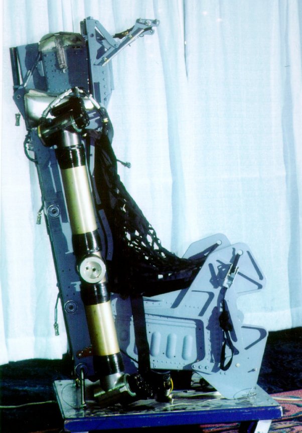
The arm nets and leg restraint system of the 4th Generation demonstrator were preset in the deployed position as was the intertia reel in the retracted
position. Since the demonstrator was mainly proving the controlled thrust, it was felt that the additional complications of developing these mechanisms
concurrently were best avoided. The arm nets and leg restraints worked well. Another mechanism unique to the seat was the head brim. This device mounted
on the headrest was designed to serve two functions. First, it was designed to provide aerodynamic isolation from the airflow over the aircrew's helmet.
Second, using a set of lines from the front edge of the extension down to the shoulder section of the aircrew harness it provided resistance to sideward
movement of the aircrew's head. The aerodynamic isolation was used to prevent the effect of the relative wind providing a lifting force on the airman's
helmet that would be transmitted to his/her neck. At seat/man separation, the brim was automatically retracted.
Although the CREST and 4th Generation programs have been closed, the CREST office is still open and developing further advances in seat design.
1 / 7
3/4 Left View
2 / 7

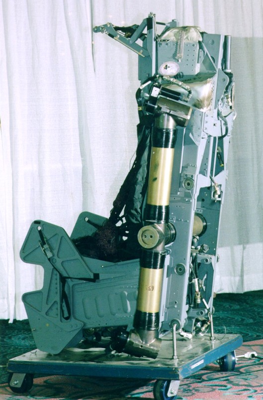
Left Side
3 / 7
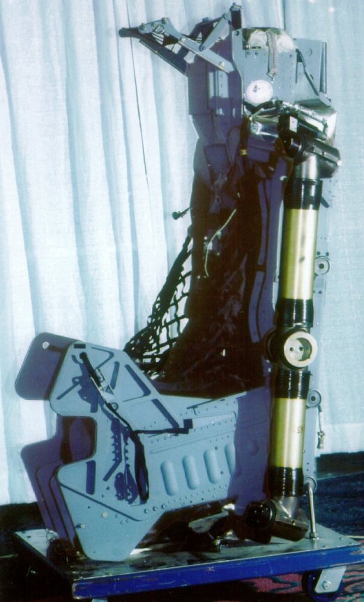
Left view. Shows arm nets and brow
pad well.
4 / 7
Right Side
5 / 7

3/4 Right View
6 / 7

3/4 Right Rear View
7 / 7
3/4 Left Side
❮
❯
This ejection seat was on display at theSAFE Association History of Escape Systems and the
Evolution of Manikins Display during the SAFE Association 40th annual Symposium, October 2002