Martin-Baker Mk US18E Seat

Mk US18E Seat


The Martin-Baker Mk. 16-series of seats has been in use for several years now and is the only seat available for the F-35 JSF. This seat is an extension of that program for use in the Block 70 F-16 aircraft. The F-35 JSF Mk. US16E seat is covered on this page for more details

Structure and Propulsion

This seat was redesigned to be more narrow due to the limitations of the existing cockpit on the F-16. By narrowing the beams and making an interface plate with the cockpit side portion of the ejection system they were able to fit the seat using the existing mounting points. A major change wasa to the headrest area, narrowing the headbox and moving more of it aft of the rails in order to improve the ability of the pilot to look over the shoulder during air combat maneuvering.
The head and neck system from the Mk 16 was retained with just a different cover. The aerodynamic plate on top has changed in size and shape though. The seats shown here may have some mockup parts installed such as the oxygen gage, however they are fully representative of the installed seats. One unique feature of the Martin-Baker implementation is the seat locking system. All ejection seats have the same concern, which is they must be locked into the aircraft during normal operations, including inverted and negative-G flight, but must be released on seat firing to exit the aircraft cleanly without loss of energy from the catapult system. In this case the hot, expanding gas from the catapult cartridge pressurizes the tubes and this forces an internal plunger upwards at the top of each tube, which releases the latches holding the inner tubes in position. This acts to ensure the catapult pressure has been reached equally in both tubes and is ready to begin seat movement.

As the seat rises up the tubes it actuates the digital electronic sequencer mounted at the base of the rail assembly which begins to assess the ejection conditions. The sequencer determines the Mode of ejection based on speed and altitude. The speed mode is determined by accelerometers instead of the more traditional pitot/static system that is in use for other seats. It has five modes from 0-0 up to high altitude and speed. The sequencer will chose the deployment time of the drogue gun, and man-seat-separation as described below.

Aircrew Protection
Aircrew Protection is a key design objective of the Mk. 16 series and the US-16E uses head and neck protection that is based on an airbag-like system. This system deploys three inflatable devices, two on the sides of the aircrew's neck, and the third above the head. They work to keep the head aligned and prevent aerodynamic lift on the helmet to keep the head forces within tolerance. One of the highest risks for aircrew injury or death during high speed ejections is aerodynamic forces on the head and neck.

The seat also deploys an aerodynamic plate on the top of the parachute pack to provide airflow control as well. This plate is somewhat different in size and shape from the JSF seat version.

The seat is equipped with limb restraints in the form of active arm restraints, and passive leg restraints. These terms refer to the aircrew's action upon cockpit entry. Previous Martin-Baker seats required the aircrew to don leg and arm restraint garments or straps. The leg straps are referred to as garters and are worn on the legs often in two positions, one below the knee, and the other above. Upon cockpit entry the aircrew would have to locate the seat lanyards and manually route them to each of the garters and back to the seat. The passive system instead consists of a pair of lanyards that are routed around the leg tunnels under the instrument panel from the sides of the seat and back to the front of the seat bucket to the lanyard snubber system under the seat. On ejection the lanyards which are connected to the cockpit floor begin to pull tight as the seat rises. The motion causes the lines to pull back around the calves and snug them against the seat pan to help prevent limb flail.

The arm restraints are considered active devices as the lanyards from them need to be connected to the seat manually on cockpit entry. The lanyards are connected to the Quick-Release-Box (QRB) with the rest of the harness straps. On ejection these are routed between the thighs and act to pull the arms in towards the center of the body during seat motion as the seat rises to exit the cockpit.

The QRB is part of the integrated harness system on this seat, one of the major changes to US seats in decades. This seat follows the International standard of having the harness as a part of the seat. US aircraft tend to be equipped with a body-worn torso harness. The advantage to this is that the US harnesses can be tailor fit to an aircrew. The integrated harness system requires that on cockpit entry the aircrew must adjust their harness straps to appropriate tightness. One advantage of this system is the QRB is fixed to the seat and acts as a negative-G restraint system to prevent the aircrew from floating above the seat during inverted or negative G flight.

After ejection the sequencer selects one of five modes from 0-0 to high altitude, high speed. The sequencer uses accelerometers to determine the speed mode and barometric sensors for the altitude. During a 0-0 ejection the seat will deploy the parachute nearly immediately followed by rapid seat man separation. The parachute headbox is launched by a mortar charge and provides a line first deployment of the main recovery parachute. At low altitudes and airspeed the mode selection would provide similar deployment modes. As the speed increases the sequencer fires the drogue rocket to rapidly deploy the drogue chute. This provides stabilization during the initial deceleration of the seat. High modes will retain the drogue, but inhibit the deployment of the main parachute and seat man separation until about 18,000 feet where the occupant can breathe without supplemental oxygen. Oxygen on the Mk. US16E seat is provided by a large tank below the headbox.

I'd like to thank the Martin-Baker team that gave me access to the seats, allowed me to take photographs and freely answered questions on the design and operation to the best of their abilities.

1 / 11
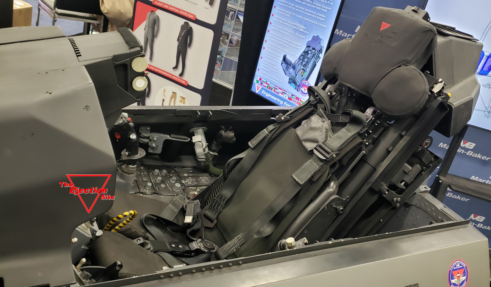
Overview of an installed seat in a F-16 cockpit
2 / 11
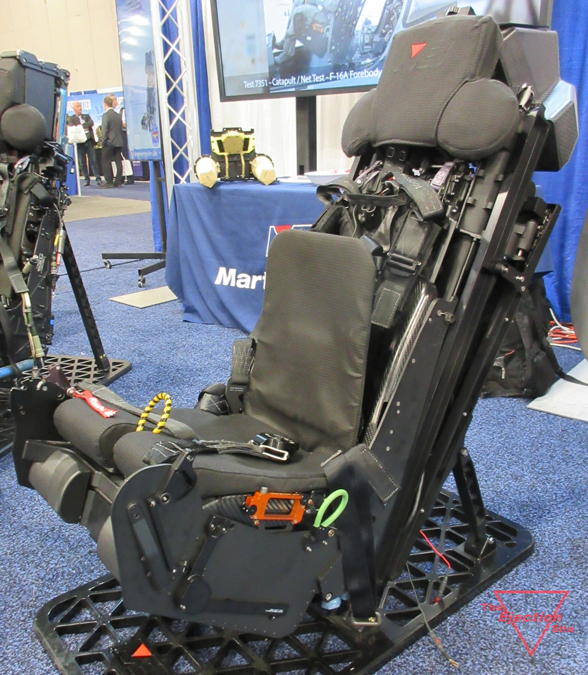
3/4 left side
3 / 11
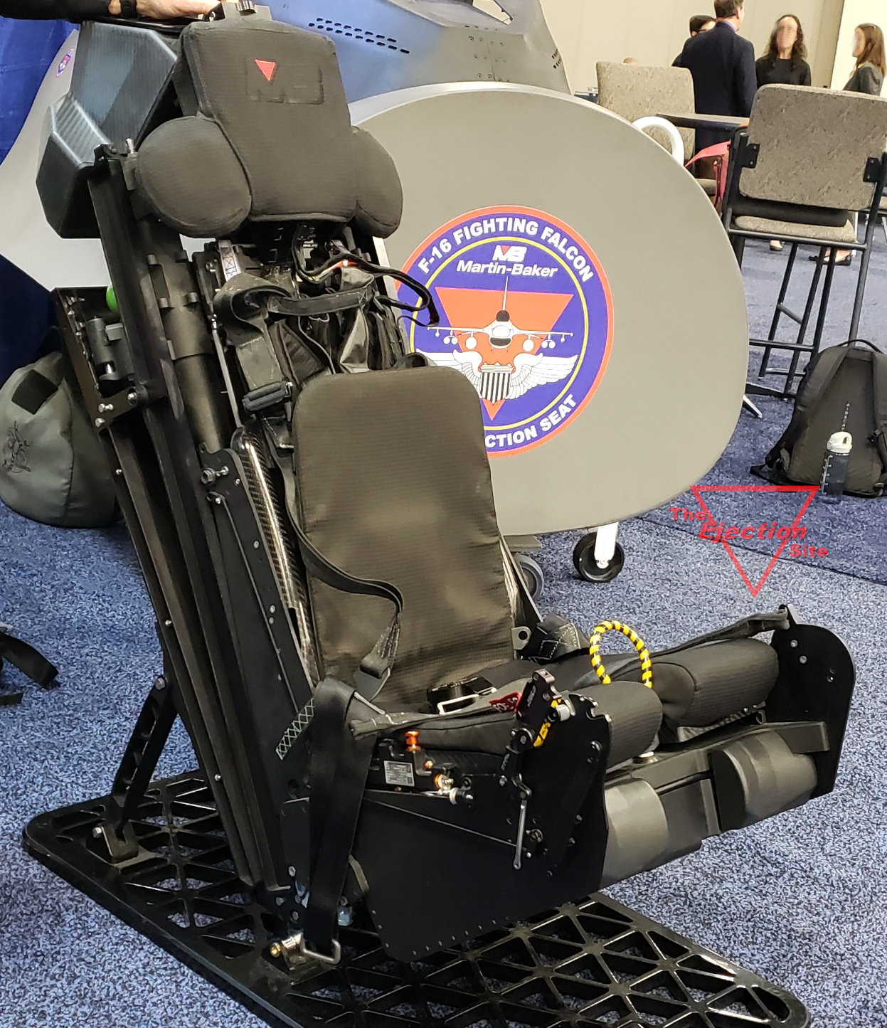
3/4 right side
4 / 11
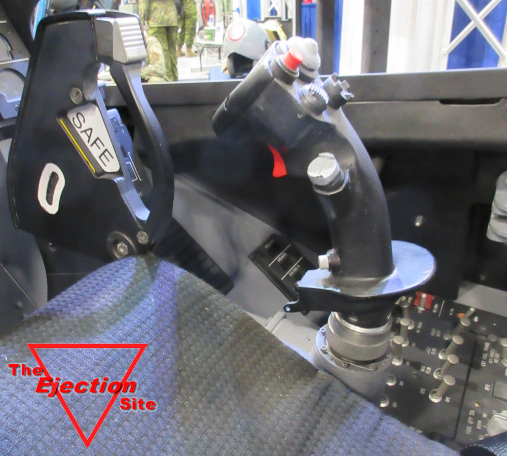
The large SAFE/ARM/MOH handle
5 / 11
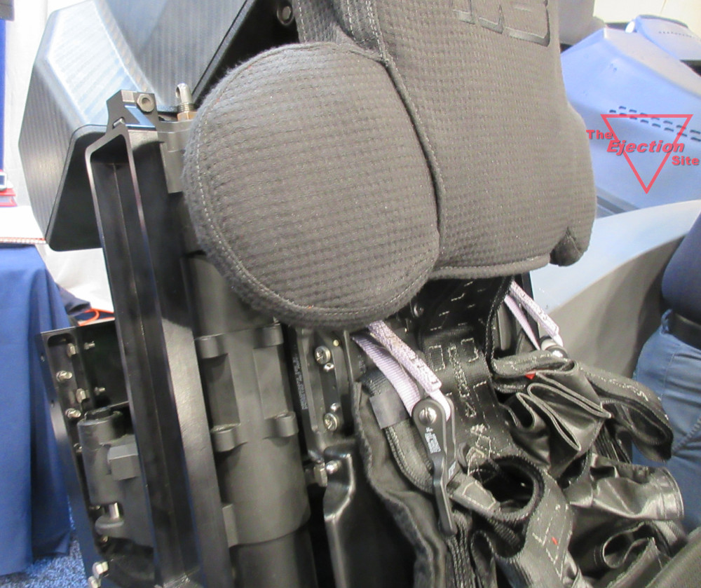
Details of the shoulder harness and inertia reel attachment area. Note also the headrest cushions.
6 / 11
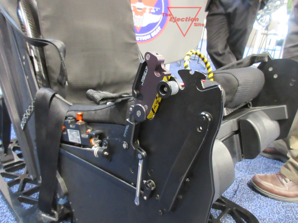
Optional SAFE/ARM handle design. To the rear under the lap strap
the edge of the rocket mount cover can be seen.
7 / 11
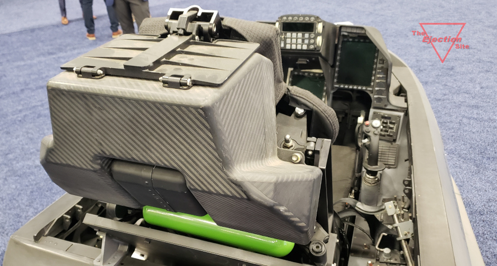
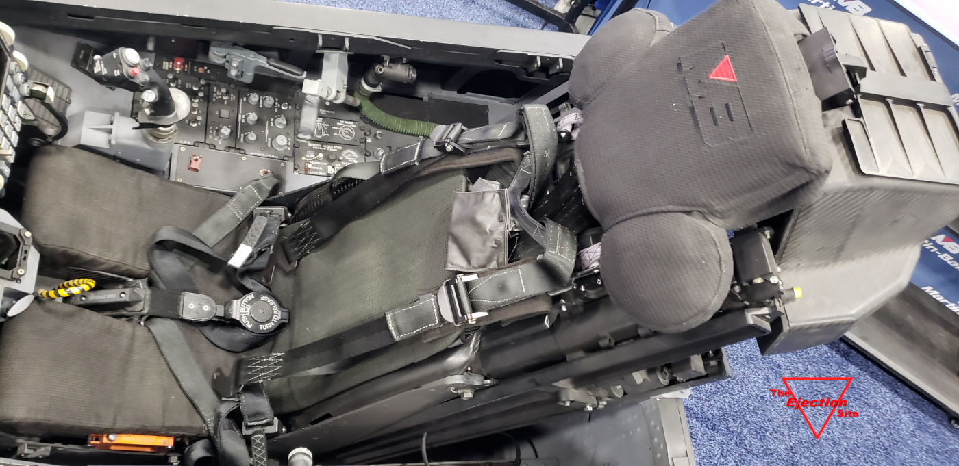
A look down the right side. Note the aero plate flat on the top of the parachute container.
The size of the oxygen tank is clearly shown.
8 / 11
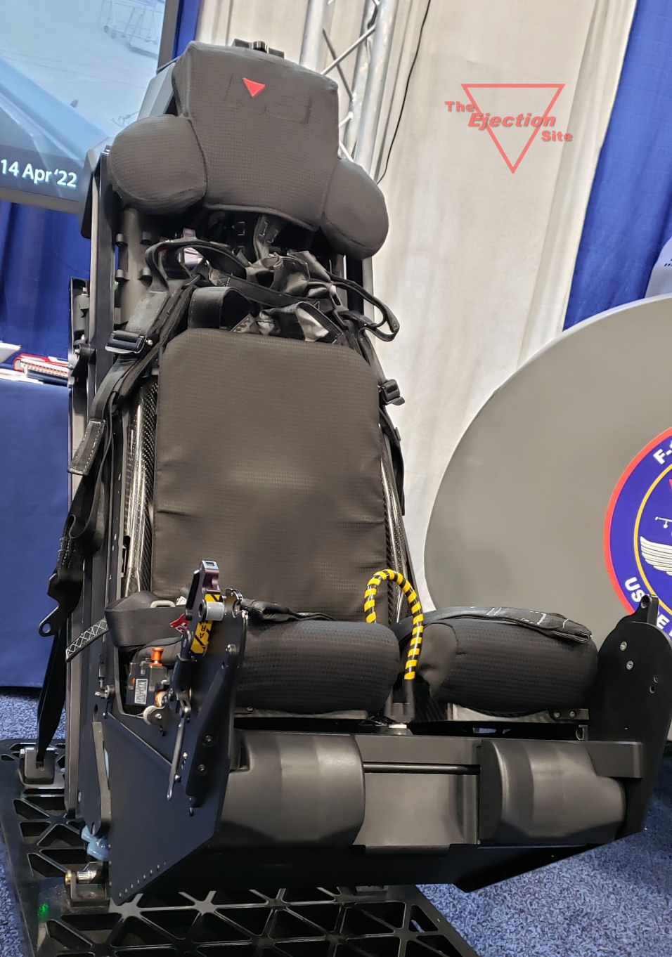
Low angle view of the front right. Note the leg restraint lines were not installed in this display seat
9 / 11
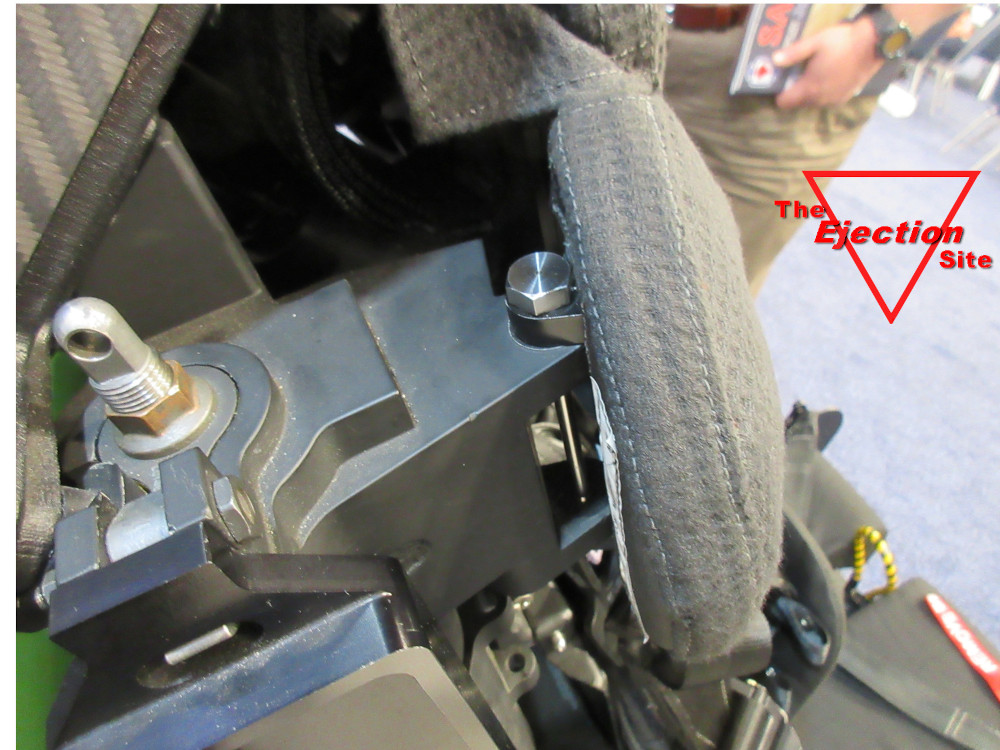
Seat top latch detail
10 / 11
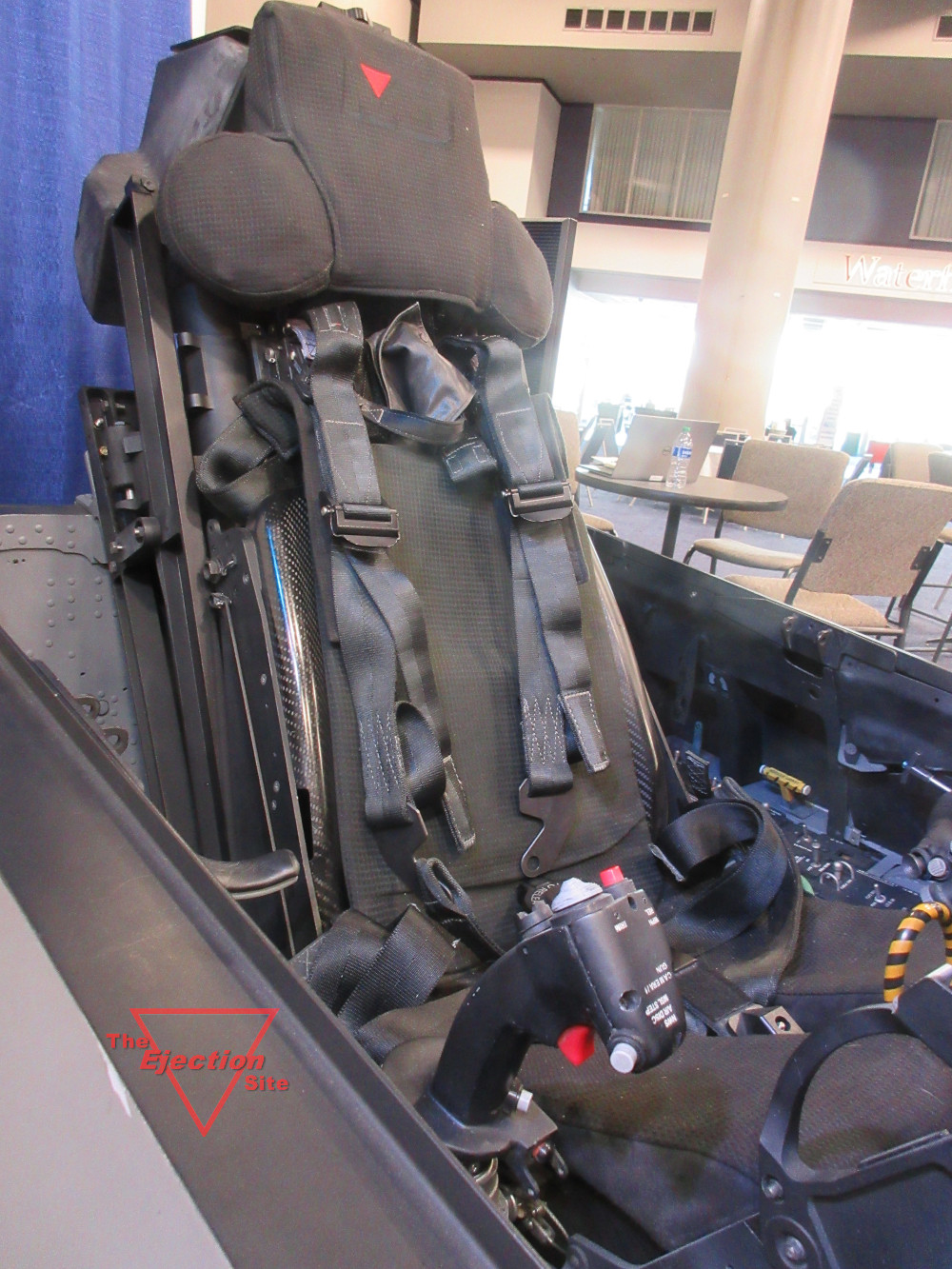
Cockpit installation shown from the right side- view 1
11 / 11
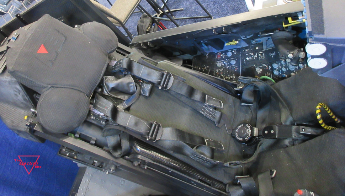
Cockpit installation shown from the right side- view 2
The Ejection Site Home
Send email to Kevin