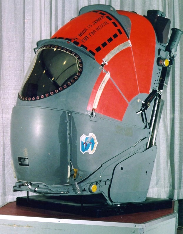
The capsule was designed to be decellerated and controlled on initial ejection by a drogue parachute and set of finned arms that were folded down along the sides of the back of the capsule. The picture above shows the fins at the base of the rear of the closed capsule. This particular example is the pilot's version as shown by the larger window and the square plate in the bottom of the capsule (visible in some of the open pictures.) This square plate covers the opening where the control stick of the aircraft would be mounted. This stick had a control for retarding the throttle to aid in descending to an altitude where the capsule could be re-opened in the case of an encapsulation due to depressurization.
This particular example has the leg retractor/lifter system in a retracted position. The arms are secured in this mode. Photos on this page show one displayed with the leg system in the normal flight positions. Encapsulation was initiated by raising one of the armrest trigger systems. This would cause a gas system to raise the leg lifters and simultaneously the mechanism would retract the two arms with the red covers on them. These arms would strike the shin/ankle area and push them into the capsule. The clamshell would then descend to the full closed position and the seal would inflate. the capsule would then be pressurized.
Squeezing the triggers would continue the ejection procedure, first jettisoning the overhead hatch, and then firing the seat mounted rocket catapult. These capsules were independant of each other in all aspects. Any crewman could encapsulate and eject themselves. There was not sequence system so the pilot would normally call for the crew to eject in order from back to front with the pilot ejecting last.
As previously mentioned, the drogue would be deployed after ejection. This would extend the linked arms to the extended position and the capsule would be slowed to a safe speed for main parachute deployment. The 70 foot diameter recovery parachute was packed in a container under the module. Also under the container was a large 'airbag' for further impact attenuation. The entire module weighed on the order of 500lbs.
The crewman also had the ability to manually deploy the parachute if he felt the automatic systems had failed. This was done by actuating a small handle to the left of the headrest. Next to that handle was another handle for cutting the parachute risers after landing to prevent being dragged.
In case of water landing, the capsule was designed to float on its back. The small yellow circles seen on the sides of the capsule contain telescoping rods with inflatable bags to assist in floatation and stability. The crewman was to cut the seal on the central panel of the shell and slide it open to be able to float in relative comfort.
An excellent write-up on the B-58 Capsule can be found on this page.
| Front view |
| 3/4 left view (Open) |
| Closeup of headrest area |
| Back of capsule showing the aircraft services disconnections. |
| 3/4 Right rear view Note the white nylon 'slippers' that the rails engage. |
This ejection seat was on display at theSAFE Association History of Escape Systems and the Evolution of Manikins Display during the SAFE Association 40th annual Symposium, October 2002
| The Ejection Site Home | |
|---|---|
| Send email to Kevin |