| Advanced Seats | ||
|---|---|---|
| 209. | The ACES II seat | 2-1 |
| 210. | Theory of operation | 2-9 |
| ACES II Seat Maintenance | ||
| 211. | Visual inspections | 2-12 |
| 212. | Operational checkouts and adjustments | 2-20 |
The "advanced concept ejection seat," or ACES II as it is called, is designed to provide safe escape at aircraft speeds from 0 to 600 knots equivalent airspeed (KEAS) (at sea level) and from ground level to 50,000 feet. Safe escape is achieved through special features and controlled event timing. The seat provides three modes of operation that are required to get the correct elapsed time from the start of the ejection to the recovery of the crewmember under all escape conditions. The increased performance capability of this system has greatly improved the survivability of aircrews during escape from aircraft under adverse conditions throughout the flight envelope. Because of this, the ACES II system has become the standard USAF seat that is used in most of the modern aircraft in the Air Force inventory. In this unit we'll cover the ACES II system.
2-1. Advanced Seats
The ACES II seat system uses both conventional and advanced technology to recover the ejecting crew member. The heart of this system lies in post-ejection, and it is at this point that all events are electronically controlled. To give you a better understanding of the ACES II system, we'll discuss each component individually. In addition, you will be provided with some important information regarding system safetying. This will include ground safety devices, maintenance safety pins, and grounding of the seat.
209. The ACES II seat
Imagine flying along on a dark rainy night--500 feet above the ground--traveling at over 10 miles per minute. Suddenly, an emergency develops and you know you must get out of that plane immediately. In situations like this, our aircrew members rely on the escape system for their survival. Needless to say, ejection success or failure depends upon equipment reliability and how well you have done your work. The failure of just one critical component can result in the loss of an aircrew. Keep this thought in mind as we discuss the individual components that make up the ACES II system. Let's get started by looking at the environmental sensor.
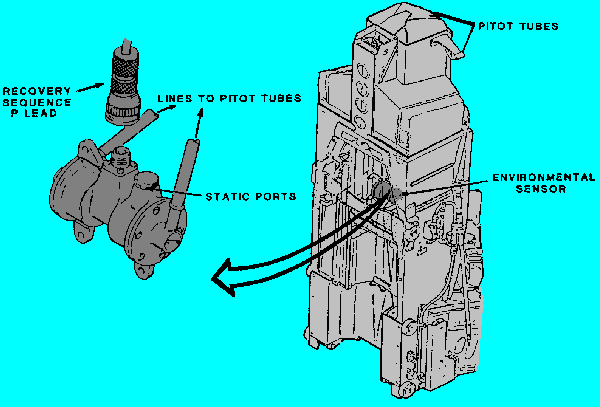
Figure 1: Environmental Sensor

Environmental sensor. The purpose of the environmental sensor is to sense seat airspeeds and altitude and send this information to the recovery sequencer. As the seat travels up the guide rail,pitot tubes located on both.sides of the headrest are exposed to the airstream. As you can see in figure 1, a static port on the environmental sensor monitors the pressure. Pitot and static pressure inputs are sensed by the speed and altitude transducers in the sensor. The transducer outputs are in turn applied to the sequencer for selection of proer recovery mode.
Recovery Sequencer. The recovery sequencer contains logic circuitry to interpret the inputs from the pitot and static inputs from the enviromental sensor. The inputs allow the sequencer to select an ejection sequence that provides the best recovery means for the full range of escape conditions.
Three modes of ejection are possible. The mode selected depends on altitude and airspeed. These possibilities are:
The recovery sequencer gets the necessary electrical power from four thermal batteries located within the sequencer. Two of these batteries are gas-fired by the rocket catapult and charge capacitors that send the electrical signals to fire the other two thermal batteries when the proper altitude parameters are reached. These batteries provide the power to operate the timing circuits. They also provide electrical initiation signals that actuate subsystem ballistic devices. The thermal batteries are dormant and there is no electrical input or output from the recovery sequencer until bleed-off pressure is provided by the rocket catapult. Once activated, information concerning speed and altitude is gathered and interpreted, and the time delays are selected. However, no post-ejection events will occur until the sequence start switch is closed.
A battery indicator window is used to determine the serviceability of the thermal batteries. A white indicator indicates the batteries are serviceable, while a red indicator sticking through the window indicates that the thermal batteries have been fired and specific technical order instructions must be followed for seat removal.
Figure 2: Initiation and Subsystems
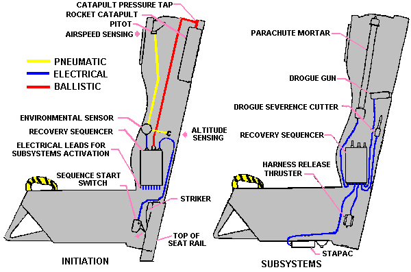
Sequence start switch. As you see in figure 2, this switch is located near the lower right-hand side of the seat and is actuated by a striker mounted near the top of the right-hand seat rail. The purpose of this switch is to start the timing sequence. The switch also acts as a safety device. In the event that the thermal batteries are inadvertently activated on the ground, the recovery sequencer cannot fire any components because the switch is open. Also, removing the seat for maintenance will not start the timing sequence because the thermal batteries have not been activated by gas pressure from the rocket catapult.
Figure 3: Pitch Stabilization
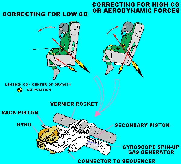
Pitch stabilization control assembly. The pitch stabilization control assembly (fig. 3), which is mounted on the bottom of the seat, contains the gyro spinup gas generator, a piston and rack assembly, a gyro rotor assembly, the vernier rocket, and the vernier rocket control pulley assemblies. When the gyro spinup gas generator is fired, it develops enough ballistic pressure to shear a pin. The pin retains the gyro spinup piston gear and rack. When the pin shears, the notched piston and rack is fired across the gear surface of the gyro rotor. This firing of the piston and rack enables the rotor to attain a speed of 10,500 revolutions per minute. Pressure continues through the piston and rack chamber to move a second piston. Starting the second piston pulls a sear from the firing device, firing the vernier rocket. The speed of the gyro rotor develops torque as the seat pitches forward or backward. This torque is used during ejection to direct the vernier rocket thrust. A pulley system aims the thrust in a direction that let's the seat maintain proper pitch attitude.
Trajectory divergence rocket (TDR). The F-15B/D/E and the F-16 B/D use a trajectory divergence rocket, installed on the lower left- or right-hand side of the seat, to prevent a collision of the seats when both seats are ejected. The F-16 A/C uses the TDR to prevent contact of the seat and recovery parachute. The TDR is fired by an electrical signal from the recovery sequencer and upon actuation, rolls the seat to the right or left, depending on the rocket installation.
Figure 4: Drogue system
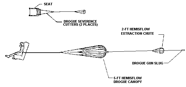
Drogue system. The drogue system slows down and stabilizes the seat during mode 2 and mode 3 ejection sequences. Because the drogue system is not needed during mode 1 ejection sequences, the drogue gun will not fire in this mode. The ACES II seat uses a drogue gun, which is electrically fired by the recovery sequencer as the seat reaches the top of the guide rails. Firing the drogue gun propels a slug to the rear which unlatches the drogue compartment cover and withdraws a 2-foot diameter extraction chute. The chute is withdrawn by means of a yoke line fastened between the slug and the chute. You can see in figure 4 that the extraction chute inflates right away and deploys a 3-foot diameter drogue parachute by means of a bridle line fastened between the two parachutes.
Drogue severance cutters. Once the seat has slowed down, two drogue severance cutters, which consist of a flexible linear shaped charge (FLSC) and a detonator charge with a dual bridgewire initiator, are electrically fired at the same time by the recovery sequencer. Upon activation, the FLSC severs the applicable drogue parachute bridle which releases the drogue parachute from the seat.
Parachute mortar assembly. The mortar assembly forcibly deploys the recovery parachute. It consists of inner and outer mortar tubes. The outer tube is attached to the recovery parachute canister and the inner tube is locked to the mortar disconnect by a lock pin that is connected to the restraint release bellcrank. The mortar disconnect contains the parachute mortar cartridge which is fired by a signal from the recovery sequencer at a time determined by the mode of ejection. The cartridge develops ballistic pressure to propel the outer tube upward which pushes the canister from the seat, deploying the recovery parachute in a reefed or noninflated condition.
Pilot chute and recovery parachute. The pilot chute is packaged in a fabric enclosure at the top of the recovery parachute metal canister. The pilot chute deploys immediately to an inflated condition, except at zero speed. As the pilot chute deploys, the canister containing the recovery parachute is pulled to deploy the parachute. The suspension lines deploy first, then the canopy deploys skirt-first as the canister separates. The 28-foot diameter canopy of the recovery parachute is reefed, and contains dual reefing line cutters. The cutters are installed on opposite sides of the canopy. As the mortar outer tube moves away from the seat, lines attached between the mortar inner tube and each parachute reefing line cutter fire the cutters. After approximately 1.15 seconds, the reefing line is cut by the cutters, allowing the recovery parachute to fully deploy. Firing the cutters allows the parachute canopy to fully inflate. Two actuation lines are attached between the firing pins of each cutter and the applicable suspension lines as a backup. The backup lines enable the suspension lines to fire the cutters in the event that mortar extension fails to occur or the primary lanyard fails to actuate the cutters.
Restraint system. The restraint system consists of lap belts, inertia reel straps, and parachute risers. These items work together to keep the crewmember restrained to the seat until separation.
Restraint release system. The restraint release system releases the crewmember from the seat. The system consists of a bellcrank, four lock pins, and a seat pan latch. When the bellcrank is rotated, the seat pan unlatches and the lock pins are withdrawn from the lapbelts, inertia reel straps, pilot recovery chute and mortar assembly. The restraint release system can be operated by a thruster during ejection, by an emergency restraint release handle during ground emergencies (this handle is not used if seats have been modified by TCTO 13A5-56-540, Restraint Emergency Release Handle and Backup Parachute Deployment System Modification), or by an equipment service release cable during maintenance.
Release thruster. The harness release thruster is electrically fired by the recovery sequencer. The thruster achieves crewmember separation by rotating the harness release bellcrank. This action pulls the lap belt and inertia reel strap locking pins and unlatches the seat pan. The thruster also unlocks the mortar assembly from the seat and allows for automatic deployment of the pilot and recovery parachutes in the event the mortar fails to fire during post-ejection. This backup feature isn't needed on seats modified by TCTO 13A5-56-540.
Figure 5: Survival Equipment
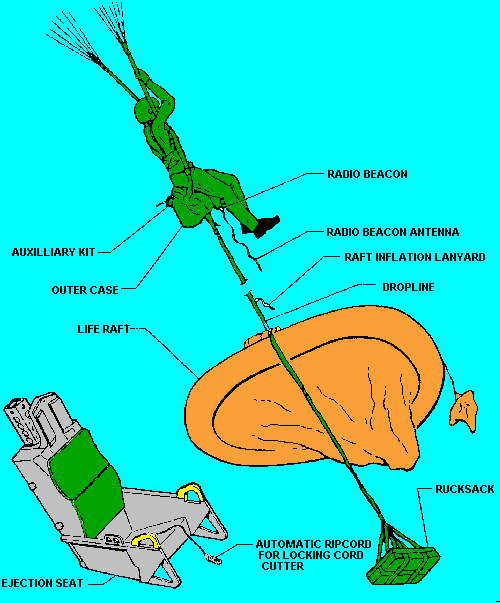
Survival kit. During crewmember separation the seat pan pivots.up and forward to allow withdrawal of the survival kit. The survival kit consists of a fabric case that houses the life raft, rucksack, and an auxiliary kit. In figure 5, you see that the life raft and rucksack are attached to the survival kit case by a dropline. The auxiliary kit is secured inside the survival kit and stores items that are needed to be retained by the crewmember. Also, the radio beacon transmitter is stored inside the survival kit and stays attached to the crewmember. A control lever, located on the front edge of the seat pan, allows the crewmember to select automatic or manual deployment of the kit. If automatic operation is selected, all of the equipment will deploy 4 seconds after crewmember separation in the configuration shown in figure 5. However, if manual operation is selected, the survival kit will stay together and remain attached to the crewmember.
Emergency oxygen system. During ejection, a lanyard attached to the aircraft floor, is pulled actuating the oxygen bottle to provide the crewmember with 10 minutes of oxygen during post-ejection. In addition, an emergency oxygen ring is provided for manual operation of the oxygen system should the automatic system fail during ejection or the normal aircraft oxygen system fail during flight.
210. Theory of operation
In the preceding section, we looked at some of the components that make up the ACES II ejection seat. Now that you have a general knowledge of these components, let's look at how they function together during an ejection.
Initiation. Pulling the firing control handles fires the ejection initiator which provides ballistic pressure to start the seat and canopy sequencing system. This system provides a time delay that allows the canopy to jettison before the rocket catapult. As the rocket catapult fires, pressure from the catapult is applied to a percussion device in the sequencer. Remember, the batteries provide no electrical power to operate the sequencer until they are fired by the hot gases the catapult.
As the seat travels up the rails, pitot tubes are exposed to the airstream. A static port on the environmental sensor monitors the pressure. Pitot and static pressure inputs are sensed by the speed and altitude transducers in the sensor and are supplied in turn to the sequencer to select the proper mode of ejection. The emergency oxygen supply is started by a lanyard connected between the oxygen cylinder and the cockpit. As the lower part of the seat nears the top of the guide mils, a sequence start switch on the seat is tumed on where switch actuating bellcrank contacts a striker on the right-hand guide rail. After a 0.18-second delay the sequencer provides an electrical signal that fires the gyro spinup gas generator. The generator develops enough pressure to shear a retaining pin. After the pin shears, the geared piston and rack are fired across the geared surface of the gyro rotor which develops a speed of 10,500 RPM to direct the thrust as the seat pitches forward or backward by means of a pulley system. The pressure then continues through the piston and rack chamber to move a second piston which pulls-a sear from the vemier rocket firing device, firing the rocket.
After a .040-second delay, the sequencer provides a signal that fires the trajectory divergence'rocket on certain seam. The start of the other components depends on the mode of operation selected by the sequencer.
Mode 1 operation. Mode 1 operation is selected for speeds of less than 250 knots (KEAS) (at sea level) and for altitudes of 0 to 15,000 feet (nominal). Mode 1 operates minus extraction chute or drogue chute deployment. The mortar is fire~econd after the sequence start switch operates. As the mortar propels the pilot chute and recovery parachute away from the seat, the pilot chute is deployed, a 1.15-second time delay in each reefing line cutter is started. Even though the drogue parachute has not been deployed, the drogue severance cutters are fired 0.15 seconds after the recovery parachute mortar fires. 0.25 seconds after the mortar fires, the restraint release thruster fires and rotates the bellcrank pulling the locking pins that secure the lap belts and inertia reel straps. As the recovery parachute deploys, the crewmember and survival kit are separated from the seat which activates the radio beacon remote switch. When the reefing line cutters fire (1.15 seconds after the mortar fires), the recovery parachute fully inflates. If automatic survival kit deployment has been selected, the kit will open 4 seconds after seat and person seperation allowing the life raft and rucksack to deploy.
Mode 2 operation. Mode 2 operation is selected for speeds above 250 knots (KEAS) (at sea level) and for altitudes of 0 to 15,000 feet. Extraction chute and drogue Chute deployment begin at the start of the recovery sequence. An electrical signal from the sequencer fires the drogue gun cartridge which propels the slug from the gun. The drogue gun slug deploys the extraction parachute which deploys the drogue parachute. The mortar is fired by a signal from the sequencer after the extraction and drogue chute deploy. The drogue severance cutters are fired by the sequencer 0. 15 seconds after the mortar is fired. Recovery parachute deployment and seat and person seperation then occur as described for mode 1.
Mode 3 operation. Mode 3 operation depends on speed and altitude. During mode 3 operation, the sequence of events occur as described for mode 2 except deployment of the pilot chute and recovery parachute, seat and person separatipn, and firing of the drogue severance cutters are delayed until mode 2 speed and altitude conditions are met.
Parachute deployment/seat and person separation systems. Prior to accomplishment of TCTO 13A5-56-540, if the automatic recovery sequence is not completed and/or started, backup systems operate as follows:
After accomplishment of TCTO 13A5-56-540, if automatic firing of the parachute mortar is not initiated by the primary mortar cartridge, a backup mortar cartridge can be used to initiate the parachute mortar. The crewmember initiates the manual mode by pulling up on the Emergency Manual chute handle. This action activates a thermal battery via a cable assembly that releases a firing pin. The firing pin strikes a primer in the emergency power supply battery. The resultant electrical pulse from the battery ignites the backup mortar cartridge ballistically deploying the parachute.
| The Ejection Site Home | |
|---|---|
| Send email to Kevin |